Apparatus for increasing turn rate of operational amplifier

An operational amplifier and slew rate technology, applied in the field of operational amplifiers, can solve problems such as large quiescent current, complex circuit structure, low power consumption, and high slew rate difficulties

Active Publication Date: 2009-01-07
FORCELEAD TECH
View PDF0 Cites 6 Cited by
  • Summary
  • Abstract
  • Description
  • Claims
  • Application Information

AI Technical Summary

Problems solved by technology

Therefore, the push-pull output stage consumes a lot of quiescent current, and it is very difficult to meet the goals of low power consumption and high slew rate
In addition, the circuit structure is also relatively comple...

Method used


Image

  • Apparatus for increasing turn rate of operational amplifier
  • Apparatus for increasing turn rate of operational amplifier
  • Apparatus for increasing turn rate of operational amplifier

Examples


Embodiment Construction

[0015] Here, the detailed content and technical description of the present invention are further described with examples, but it should be understood that these examples are only for illustrative purposes, and should not be construed as limitations on the implementation of the present invention.

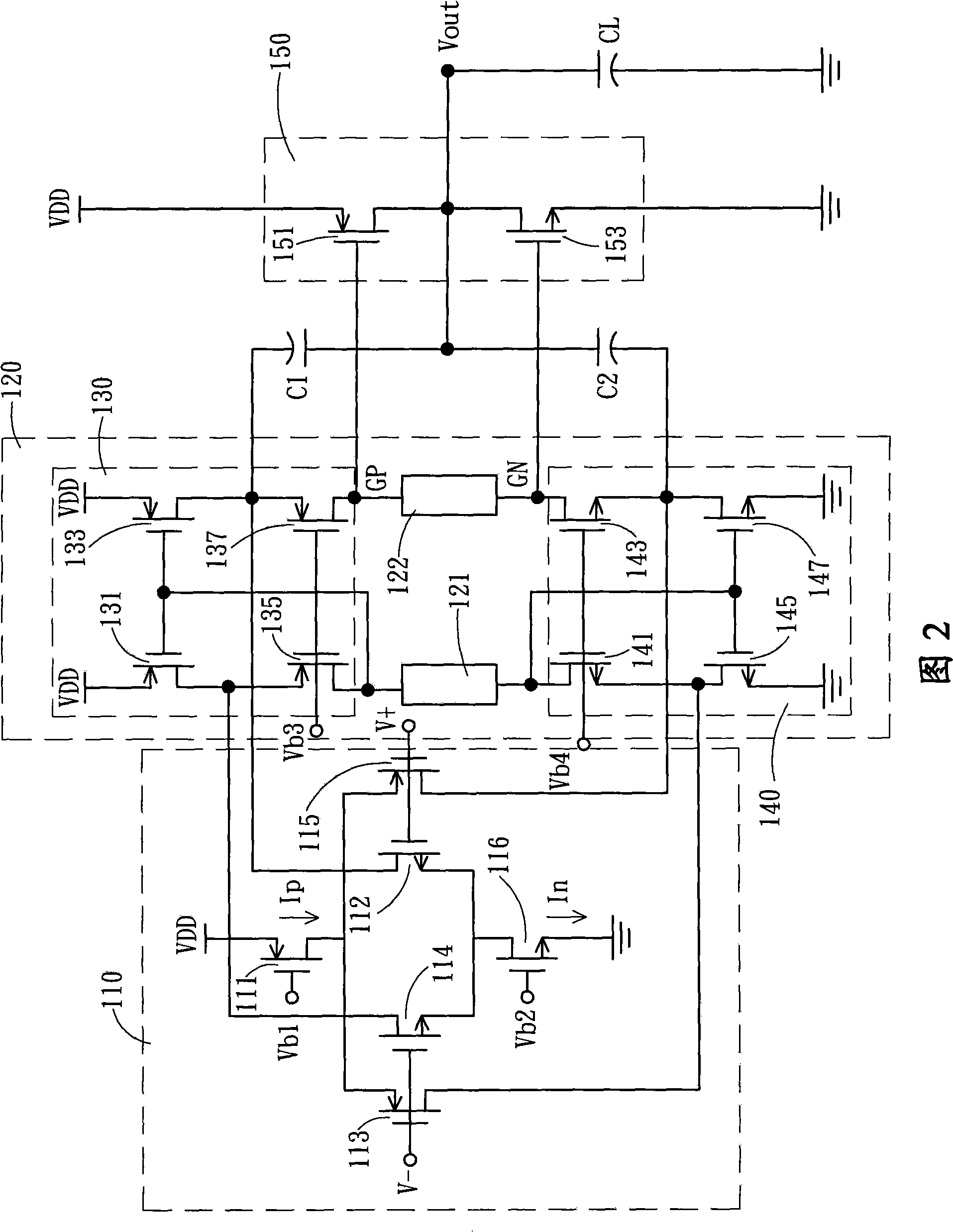
[0016] Please refer to FIG. 2 first, which is a schematic circuit diagram of a general Class AB (Class AB) operational amplifier. A general Class-AB (Class-AB) operational amplifier is an operational amplifier with a push-pull output stage, and the operational amplifier includes an input stage (Input Stage) 110 , a Class-AB (Class-AB) control stage 120 and an output stage 150 . The input stage 110 includes a P-type input pair composed of P-type transistors 111, 113 and 115, and the P-type transistor 111 is its current source; and an N-type input pair composed of three N-type transistors 112, 114 and 116, N-type transistor 116 is its current source. The Class-AB (Class-AB) control st...


PUM


Abstract

The invention relates to a device for increasing the turning rate of an operational amplifier, an auxiliary output device and an auxiliary control device are added after the output stage of the operational amplifier, the current of the output stage is mirrored by the auxiliary control device and is compared with the reference current, thereby generating an auxiliary push-pull control signal to control the auxiliary output device; when the voltage level of an output signal is not equal to the voltage level of an input signal essentially, the auxiliary control device is controlled to start the auxiliary output device to provide an auxiliary output current to an output end, when the voltage level of the output signal is equal to the voltage level of the input signal essentially, the auxiliary output device is closed.

Description

technical field [0001] The present invention relates to an operational amplifier applied to a unit-gain input buffer for negative feedback, especially a device for increasing the slew rate of the operational amplifier by using mirror current comparison to control the auxiliary output. Background technique [0002] In order to achieve high slew rate (Slew Rate) requirements in known operational amplifiers, methods include increasing the current of the differential input pair (Differential Input Pair) or reducing the compensation capacitor; however, increasing the current of the differential input pair will increase the quiescent current consumption, Reducing the compensation capacitor sacrifices the stability of the op amp. [0003] Another known method is to use an error amplifier (Error Amplifier) ​​to drive a common-source output stage, that is, a push-pull (Push-pull) output stage output, that is, to add an additional circuit to achieve the purpose. Please refer to FIG. ...

Claims


Application Information

Patent Timeline
IPC IPC(8): H03F1/02
Inventor 俞仲威
Owner FORCELEAD TECH
Why Eureka
Try Eureka