Thermal Storage Material Microcapsules, Thermal Storage Material Microcapsule Dispersion and Thermal Storage Material Microcapsule Solid

Inactive Publication Date: 2009-07-02
MITSUBISHI PAPER MILLS LTD
View PDF6 Cites 5 Cited by
  • Summary
  • Abstract
  • Description
  • Claims
  • Application Information

AI Technical Summary

Benefits of technology

[0060]The first object of the present invention can be achieved by the first thermal storage material microcapsules of the present invention. In the first thermal storage material microcapsules of the present invention, at least one of the compounds of the general formula (I) to (III) is used as a thermal storage material. The hydrocarbon groups of each of these compounds have 6 or more carbon atoms, and the thermal storage material has an acid value of 8 or less. The first thermal storage material microcapsules therefore have characteristic features that they are not easily dissolved in dispersing media such as water and that they are not easily hydrolyzable in environments where a water content and pH are easily changed. Therefore, when they are used for a long period of time in fields where heating and cooling are repeated, stable thermal properties can be obtained and a high heat amount for melting can be maintained. Further, in the step of micro-encapsulation, most part of the thermal storage material compound forms oil drops to be encapsulated, and the encapsulation ratio is improved. Further, the resultant dispersion of the thermal storage material microcapsules is excellent in dispersion stability.
[0061]Each of the above compounds (I) to (III) has two hydrocarbon groups which may be different in the number of carbon atoms, and these two hydrocarbon groups are combined while the numbers of carbon atoms are changed so long as the they have 6 or more carbon atoms, whereby any melting point can be set as required and the above compounds (I) to (III) can be applied to the thermal storage material for use in any one of the low temperature, intermediate temperature and high temperature regions. When the above thermal storage material is used as one in the high temperature region, a high heat amount that cannot obtained with a paraffin wax can be attained, and a prompt thermal response in a phase change can be accomplished. When the above thermal storage material is used as one in the intermediate temperature region, there can be obtained a high heat amount and

Problems solved by technology

As a result, the heat-exchange efficiency is decreased or the field of use thereof has been limited in many cases.
However, although aliphatic hydrocarbon compounds having melting points in the low temperature region and high temperature region are produced in a large quantity, aliphatic hydrocarbon compounds having melting points in the high temperature region are difficult to isolate and purify, and there are few compounds that are mass-produced.
They are also expensive.
However, it has a drawback that the amount of heat for melting is low as compared with a single-compound product of an aliphatic hydrocarbon compound, presumably because it is a mixture.
Further, it is poor in phase change response when it undergoes a phase change, and when a paraffin wax in a coagulation state is heated, the temperature range from the start of melting to the completion of melting is broad.
In this case, the above hydrocarbon compound has a low heat amount for melting and is poor in phase change response when it undergoes a phase change like those which have melting points in the high temperature region.
However, although these compounds can be used in a bulk state without any problem, they have had various problems when they are micro-encapsulated by emulsifying and dispersing them.
That is, when higher alcohols or higher fatty acids are micro-encapsulated by conventional procedures, they are poor in emulsion-dispersibility presumably because the crystallization rate of these compounds is high, and there has been a problem that the ratio of effective formation of capsules (encapsulation ratio) is decreased.
Further, some of them have the problem of a characteristic odor depending upon the number of carbon atoms, and some of them are not suitable as thermal storage materials that are in particular emulsified and dispersed for use.
For example, when thermal storage material microcapsules are produced in a manner that a thermal storage material is emulsified and dispersed in water or the like as a dispersing medium, there is a problem that an ester compound obtained by a reaction between a higher fatty acid and a lower alcohol hav

Method used


Image

  • Thermal Storage Material Microcapsules, Thermal Storage Material Microcapsule Dispersion and Thermal Storage Material Microcapsule Solid
  • Thermal Storage Material Microcapsules, Thermal Storage Material Microcapsule Dispersion and Thermal Storage Material Microcapsule Solid
  • Thermal Storage Material Microcapsules, Thermal Storage Material Microcapsule Dispersion and Thermal Storage Material Microcapsule Solid

Examples


example 2

(Fiber-Processed Product Example 2)

[0151]Wearing a jacket obtained by processing the thermal storage material microcapsules in which the thermal storage material is adjusted to have a melting temperature of 18° C. and a coagulation temperature of 10° C., one stays in a room having a room temperature of 21° C. for 1 hour (at this time, the entire thermal storage material inside the thermal storage material microcapsules is melted), and then he or she goes out at an outdoor air temperature of 5° C. In this case, the temperature of the jacket is decreased due to the outdoor air temperature, and when it reaches 10° C. which is the coagulation temperature of the thermal storage material, the thermal energy stored inside the thermal storage material starts to be released, so that a temperature of 10° C. is maintained until the entire thermal storage material is completely coagulated. During this period of time, he or she wearing the jacket can feel the sense of comfortable warmness since ...

example 1

[0170]80 Parts of hexadecyl palmitate corresponding to the compound of the general formula (I) [a compound of the general formula (I) in which R1 is pentadecyl having 15 carbon atoms and R2 is hexadecyl having 16 carbon atoms] was added, with vigorously stirring, to 100 parts of 5 a % styrene-maleic anhydride copolymer sodium salt aqueous solution having its pH adjusted to 4.5, followed by emulsification until an average particle diameter of 3.0 μm was attained. The above hexadecyl palmitate had a purity of 96%, an acid value of 0.3 and a hydroxyl value of 1.0. Then, 8 parts of melamine, 11 parts of a 37% formaldehyde aqueous solution and 20 parts of water were mixed, the mixture was adjusted to a pH of 8 and a melamine-formalin initial condensate aqueous solution was prepared at approximately 80° C. The entire amount of this aqueous solution was added to the above emulsion and the mixture was stirred under heat at 75° C. for 3 hours to carry out an encapsulation reaction, and the r...

examples 2-11

[0171]Thermal storage material microcapsules according to an in-situ polymerization method were produced in the same manner as in Example 1 except that the hexadecyl palmitate in Example 1 was replaced with compounds shown in Table 1. Table 1 shows the volume average particle diameters of the thus-obtained thermal storage material microcapsules, the melting temperatures, coagulation temperatures, initial differences between the melting temperatures and the coagulation temperatures and change ratios of temperature difference of the thermal storage materials and the thermal loss ratios of the thermal storage material microcapsules.


PUM

PropertyMeasurementUnit
Temperatureaaaaaaaaaa
Percent by massaaaaaaaaaa

Abstract

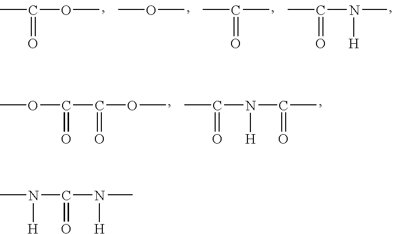
The thermal storage material microcapsules of the present invention are thermal storage material microcapsules encapsulating a thermal storage material, and the thermal storage material comprising at least one selected from compounds of the following formulae (I) to (III),
R1-X-R2  (I)
    • wherein each of R1 and R2 is independently a hydrocarbon group having 6 or more carbon atoms and X is a divalent binding group containing a heteroatom,
R3(-Y-R4)n  (II)
    • wherein R3 is a hydrocarbon group having a valence of n, each of R4s is independently a hydrocarbon group having 6 or more carbon atoms and each Y is a divalent binding group containing a heteroatom,
A(-Z-R5)m  (III)
    • wherein A is an atom, atomic group or binding group having a valence of m, each of R5s is independently a hydrocarbon group having 6 or more carbon atoms and each Z is a divalent binding group containing a heteroatom or a direct bond, the thermal storage material having an acid value of 8 or less.

Description

TECHNICAL FIELD[0001]The present invention relates to microcapsules containing a thermal storage material whose latent heat is used. More specifically, it relates to thermal storage material microcapsules that are remarkably excellent in thermal shock absorbing capability around the melting temperature and / or coagulation temperature of a thermal storage material, a dispersion of the thermal storage material microcapsules in a dispersing medium, and a thermal storage microcapsule solid formed of the above thermal storage microcapsules or a plurality of the above thermal storage microcapsules that are bonded together.BACKGROUND ART[0002]In recent years, there is demanded energy saving by the efficient use of thermal energy. As an effective method therefor, studies have been made of a method in which heat is stored by utilizing latent heat that entails the phase change of a substance. As compared with a method using only sensible heat that entails no phase change, a large quantity and ...

Claims


Application Information

Patent Timeline
IPC IPC(8): F28D19/02B32B23/14
CPCC09K5/063F28D20/023Y10T428/2982Y10T428/2998Y02E60/145Y02E60/14
Inventor IKEGAMI, KOSHIROMOURI, NOBUYOSHIISHIGURO, MAMORU
Owner MITSUBISHI PAPER MILLS LTD
Why Eureka
Try Eureka