Power transmission unit for vehicle

a transmission unit and vehicle technology, applied in mechanical equipment, transportation and packaging, gearing, etc., can solve the problems of engine operating efficiency worsening, engine cannot always operate at optimal operating points, and the number of required engagement devices is rather small, and the structure of the power transmission unit can be simplified. , the effect of reducing the size of the power transmission uni

Active Publication Date: 2016-06-21
TOYOTA JIDOSHA KK
View PDF17 Cites 6 Cited by
  • Summary
  • Abstract
  • Description
  • Claims
  • Application Information

AI Technical Summary

Benefits of technology

[0018]The present invention has been conceived noting the foregoing technical problem, and it is therefore an object of the present invention is to provide a power transmission unit for a vehicle in which a torque transmission route can be selected from a plurality of transmission routes, and to simplify a structure of the power transmission unit while improving a speed change response.

Problems solved by technology

In addition, optimum operating points of the engine are limited.
However, if a geared transmission adapted to shift a gear stage stepwise is used in the vehicle, the engine cannot be always operated at optimum operating points.
That is, if the optimum operating speed exists between the gear stages, the operating efficiency of the engine would be worsened.
In addition, fuel economy will be worsened as a result of establishing high pressure.
However, large number of engagement elements is required to establish such torque transmission route.
Therefore, the structure of the transmission is complicated and dimension thereof is enlarged.
Therefore, a shifting delay may occur during the so-called garage shifting.
Thus, according to the teachings of Japanese Patent Laid-Open No. 2000-130548, the switching operation of the dog clutch and the engaging operation of the first clutch may be delayed inevitably to deteriorate shifting response during the garage shifting.

Method used


Image

  • Power transmission unit for vehicle
  • Power transmission unit for vehicle
  • Power transmission unit for vehicle

Examples


Embodiment Construction

)

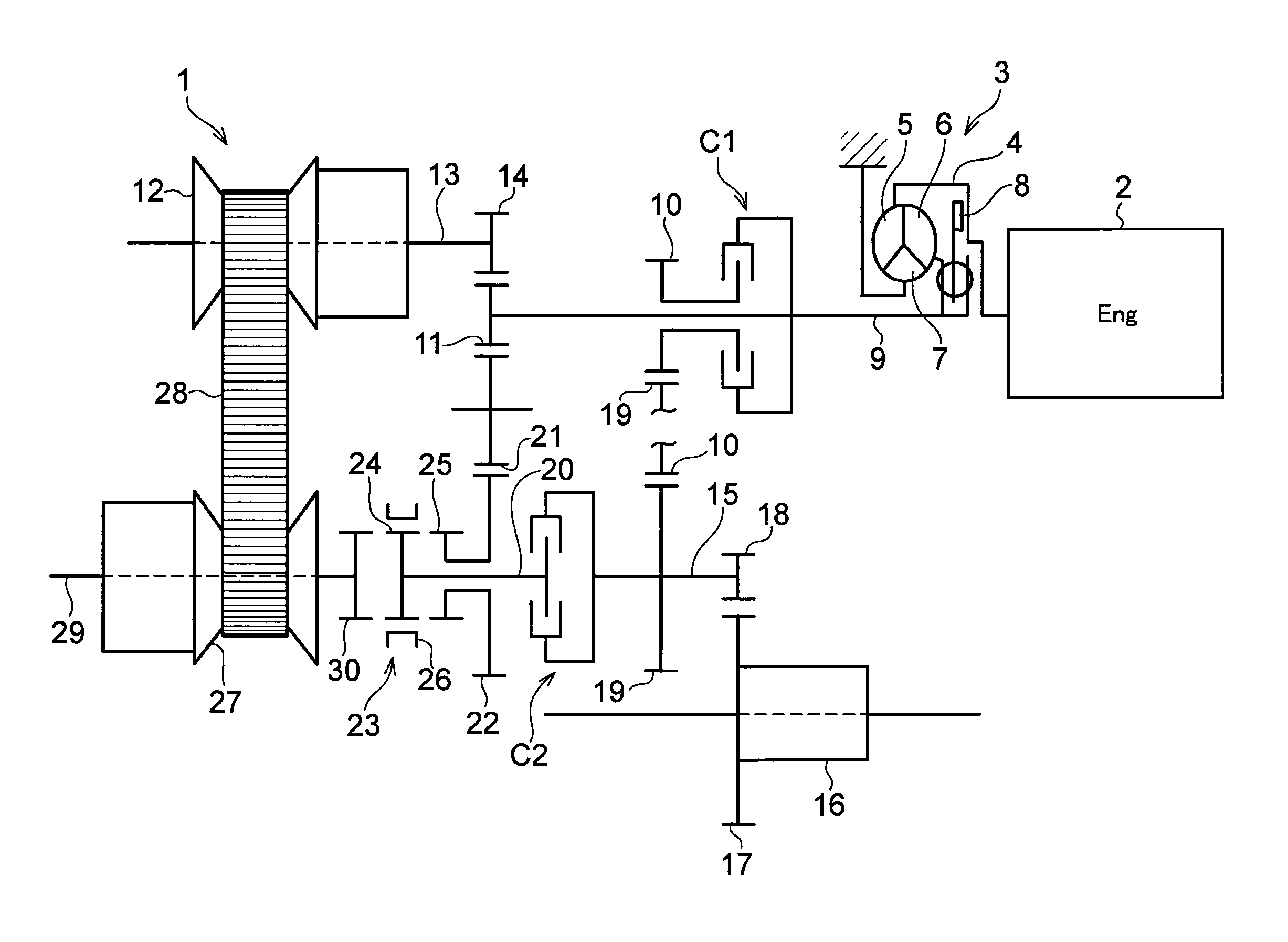
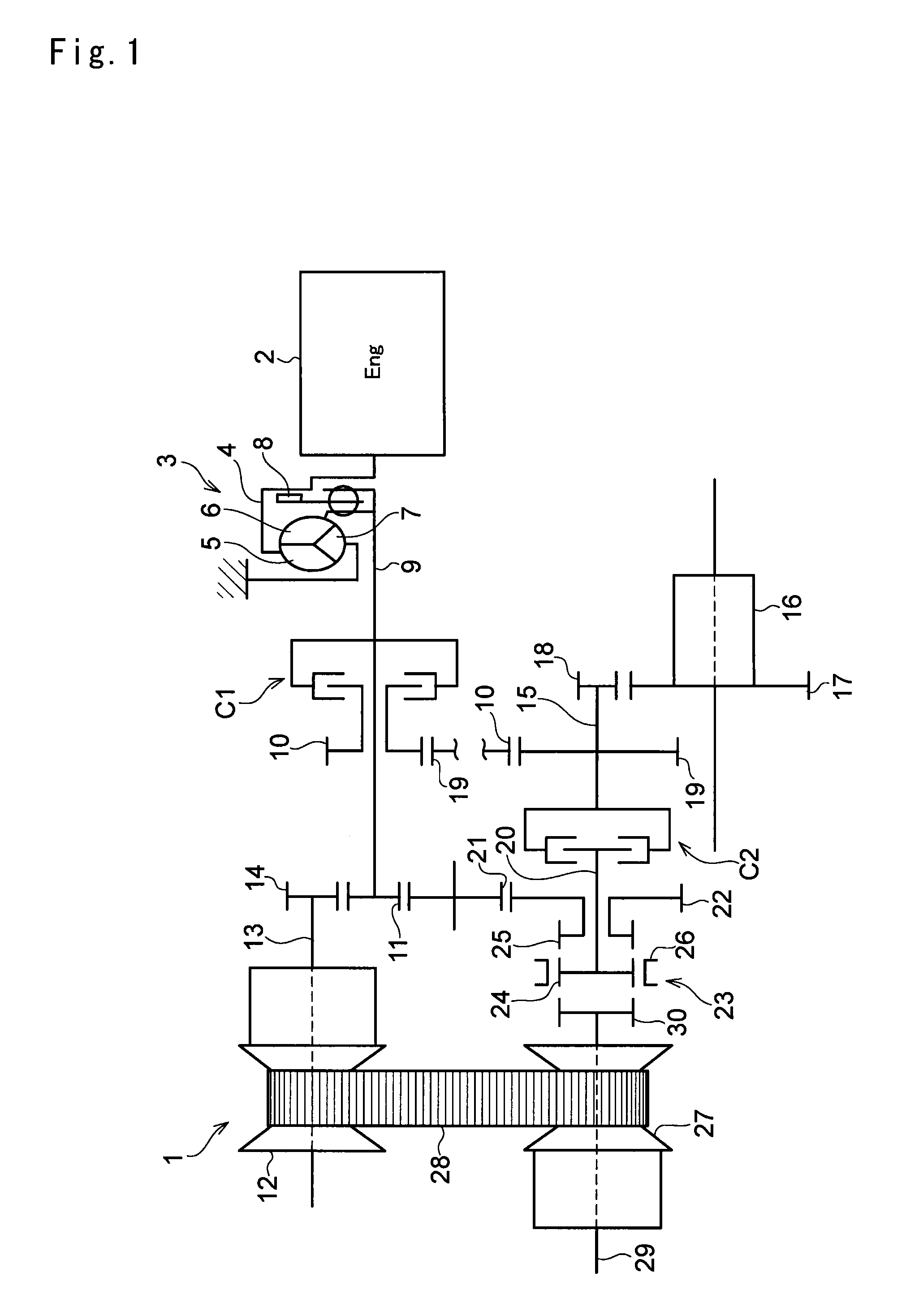
[0045]According to the present invention, there is provided a power transmission unit for transmitting a power of a prime mover such as an engine and a motor, and the power transmission unit has a speed change function. In general, this kind of power transmission unit is called a transmission or a transaxle. More specifically, the present invention is applied to a power transmission unit in which a continuously variable transmission and a gear train of predetermined speed ratio (or a gear ratio) are arranged parallel to each other between an input shaft and an output shaft. In the power transmission unit, a conventional belt-driven continuously variable transmission and a toroidal continuously variable transmission may be used. Specifically, the belt-driven continuously variable transmission is suitable for a power transmission unit of an FF layout vehicle (i.e., a front engine / front wheel drive vehicle), and the toroidal continuously variable transmission is suitable for a power t...


PUM


Abstract

A power transmission unit including a first clutch device that selectively enables and disables a torque transmitting route from an input shaft to an output shaft via a first gear train to transmit torque therethrough, a dog clutch that switches the torque transmitting route from the input shaft to the output shaft between a continuously variable speed change route in which torque is transmitted through a continuously variable transmission and a reverse route in which torque is transmitted through a second gear train, and a second clutch device that selectively enables and disables both of the continuously variable speed change route and the reverse route to transmit torque to the input shaft or the output shaft. The first clutch device and the second clutch device are separately disposed on any of the input shaft and the output shaft in a manner to be situated at different axial positions.

Description

TECHNICAL FIELD[0001]The present invention relates generally to a transmission unit for transmitting power of a prime mover of an automobile, and more particularly, to a power transmission unit comprising a transmission route including a continuously variable transmission, and another transmission route arranged in parallel to said transmission route.BACKGROUND ART[0002]Generally, an output torque of an internal combustion engine is increased with an increase in a rotational speed, but a vehicle requires a large drive force at low speed and small drive force at high speed. That is, the vehicle required opposite torque characteristic to that generated by the engine. In addition, optimum operating points of the engine are limited. Therefore, the vehicle having the engine as a prime mover is provided with a transmission to alter a sped ratio according to need so that the engine is allowed to be operated at the optimum operating points to generate drive force by altering the speed ratio...

Claims


Application Information

Patent Timeline
Patent Type & Authority Patents(United States)
IPC IPC(8): F16H37/02F16H37/06
CPCF16H37/021F16H2037/026F16H2200/0008Y10T74/19019
Inventor KOBAYASHI, DAISUKEYOSHIDA, MICHIOYOSHINO, HIROTSUGUOSADA, TOMOE
Owner TOYOTA JIDOSHA KK
Why Eureka
Try Eureka