Grain saving, directable unloader boot assembly

a boot assembly and grain technology, applied in the field of unloading grain, can solve the problems of less than the optimal amount of grain available for transportation, the maximum amount of grain cannot be loaded onto the truck, and the difficulty of doing so, so as to prevent inadvertent grain spillage

Active Publication Date: 2010-01-12
BLUE LEAF I P INC
View PDF26 Cites 25 Cited by
  • Summary
  • Abstract
  • Description
  • Claims
  • Application Information

AI Technical Summary

Problems solved by technology

Otherwise, the maximum amount of grain cannot be loaded onto the truck without subsequent maneuvering of one or the other vehicles.
That is, if the combine is mis-positioned, the grain will not flow evenly onto the truck bed, hence, less than the optimal amount of grain is available for transport on the missed side of the truck bed.
However, to do so has become more difficult over the years as the auger tubes have grown longer and longer, in order to keep pace with the ever-increasing width of modern day combine headers, which are now as wide as 42 feet or more.
Most of these prior art devices have been overly complicated, requiring many moving parts and complex operations.
Others have been simple and are either ineffective or require time-consuming, manual adjustments such as certain elongated spout attachments that are unduly sensitive to movement and difficult to control.
The complex operation, complexity of assembly, and / or complexity of disassembly, or the ineffectiveness have inhibited the devices from widespread commercial acceptance and / or the time-consuming methods for using them dissuaded their implementation.
The spout was not secure.
Furthermore, the spout was not adjustable, except by hand, which would require operators to climb up and adjust it for every change in angle desired during unloading of the feed.
The hinges for the pivot plate were located within the pattern of flow of the grain and therefore were difficult to maintain, thus incurring damage and clogging.
The deflection plate was unstable.
Additionally, like other systems for directing the discharge, there was no means to save grain from dribbling, inadvertently, out of the end of the auger after the unloading was disengaged.
Finally, the grain discharge would lose velocity as it flowed through the open funnel, thus losing efficiency.
U.S. Pat. No. 6,974,021, entitled Adjustable Grain Spout Assembly, issued Dec. 13, 2005, to Craig Boevers, disclosed a complex pivot spout assembly with many complicated attachments and parts which led to more frequent breakdown and damage.
A second unloading problem in addition to the directability of the grain discharge, is that of dribbling grain.
Such loss is expensive and unsightly.
Attempts to solve the problem have included shutters, doors, valves, etc. which have ancillary moving parts and extraneous components which add even more expense to the combine unloader.
The problem is that such spring loaded impingements are not strong enough to hold grain residue over time, and tend to inadvertently release and allow grain to dribble out when weakened.

Method used


Image

  • Grain saving, directable unloader boot assembly
  • Grain saving, directable unloader boot assembly
  • Grain saving, directable unloader boot assembly

Examples


Embodiment Construction

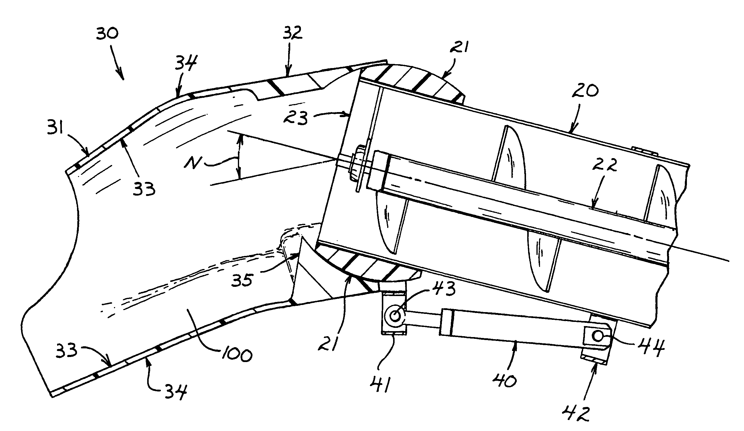
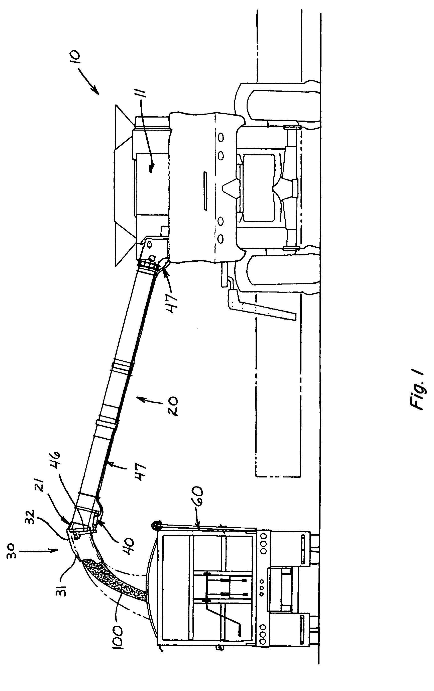
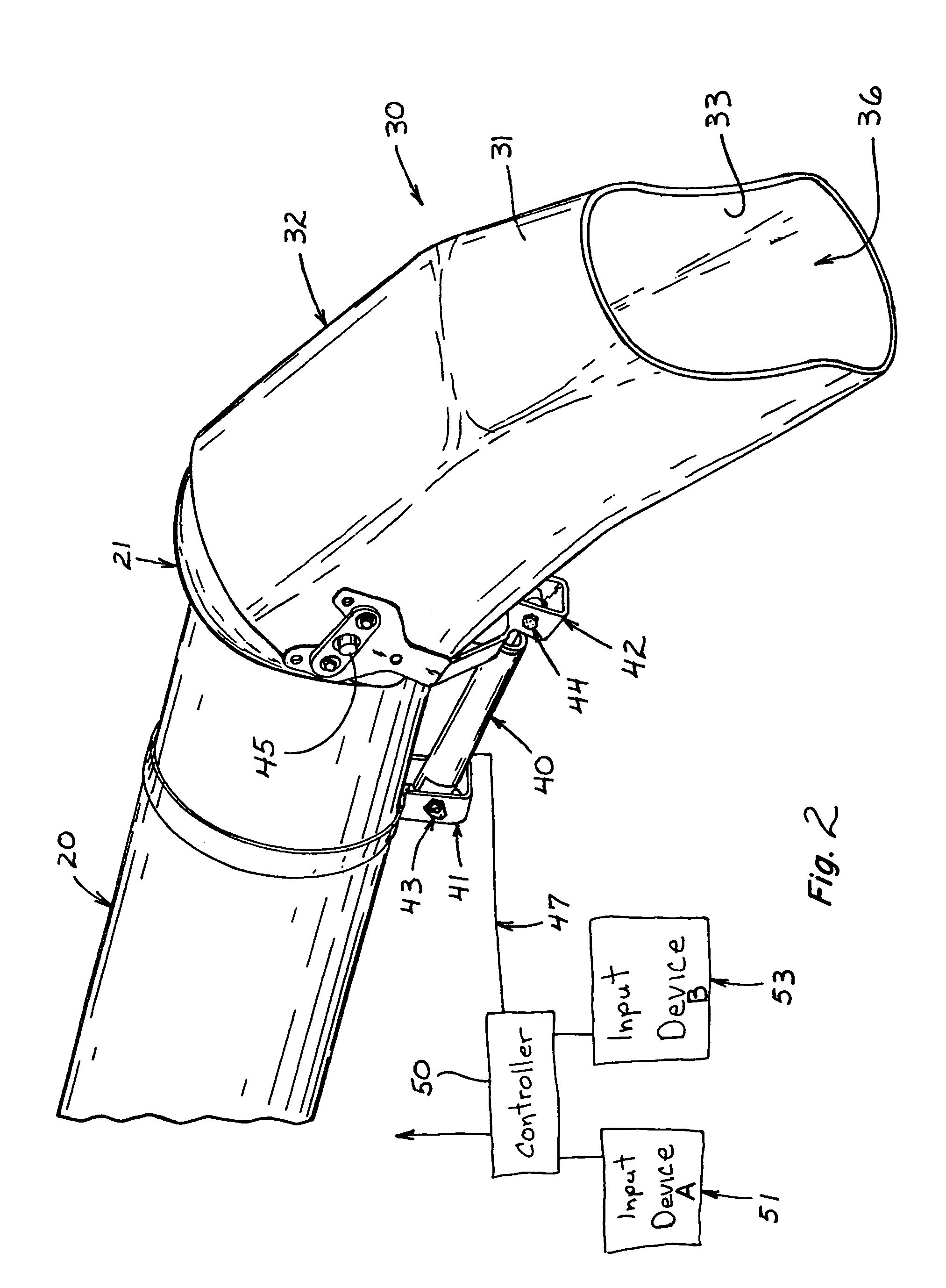
[0019]Referring now to FIG. 1, combine harvester 10 has its unloading auger tube 20 transversely extending and fully deployed as it unloads grain 100 through discharge boot 30 and into bed of truck 60. Boot 30 can have any convenient shape. Preferably, it is generally cylindrical, but can be more boxy with edges, or venturi-shaped, etc. The opening of auger tube 20 at its distal end is peripherally sealed by a joint member 21 which hingedly engages portion 32 of boot 30, which portion 32 interfaces the distal end of the auger tube 20. The joint member is preferably rounded or spherical, but can be cylindrical on a horizontal axis, so long as the interface between the tube 20 and boot 30 is adequately sealed. Angularly extending from portion 32 of boot 30 is spout end 31 of the boot. Signals from cab 11 of combine harvester 10, travel through conduits 47 for controlling an actuator 40, which actuator 40 pivotally moves boot 30 in hinging relationship to the unloading auger tube 20, v...


PUM


Abstract

A pivoting boot is disclosed for attachment to the unloading auger tube of combine harvesters, and serves as both a grain saving dam against unwanted grain spillage, and a directable spout. The boot permits evenly unloading grain onto, or completely filling, transportation vehicles or storage containers, without having to change the combine position, once it is staged for unloading.

Description

TECHNICAL FIELD[0001]The present invention relates to unloading grain, from the auger tube of a combine harvester, into a storage facility or a transporting truck, wagon, or other vehicle. It particularly relates to a grain saving boot assembly for the auger tube, and a dribble-proof method for directionally unloading grain, from the auger tube, when deploying the boot.BACKGROUND ART[0002]Unloading of grain from combine harvester storage bins, by way of an auger discharging said grain through a tube and spout, has had, inter alia, two continuing inefficiencies over the years, i.e. directability and spillage by dribbling.[0003]First, when loading grain onto, for example, the bed of a truck, from an auger, generally the truck must be positioned so that the downspout of the auger tube is centered in relationship to the bed of the truck. Otherwise, the maximum amount of grain cannot be loaded onto the truck without subsequent maneuvering of one or the other vehicles. That is, if the com...

Claims


Application Information

Patent Timeline
Patent Type & Authority Patents(United States)
IPC IPC(8): B65G33/14B65G33/22
CPCA01D41/1217B60P1/42
Inventor VEIGA LEAL, JOSE LUIZSCHROEDER, JAY D.FINLEY, BRYAN B.JUNGES, LUIZ G.
Owner BLUE LEAF I P INC
Why Eureka
Try Eureka