Terminal block and test pad for an HVAC controller

a terminal block and controller technology, applied in the direction of contact members penetrating/cutting insulation/cable strands, instruments, transportation and packaging, etc., can solve the problem of no easily accessible site for electrical testing of the terminal

Active Publication Date: 2010-01-12
ADEMCO INC
View PDF26 Cites 53 Cited by
  • Summary
  • Abstract
  • Description
  • Claims
  • Application Information

AI Technical Summary

Problems solved by technology

With quick-connect or screwless terminal blocks, there is no easily accessible site to electrically test the terminal.

Method used


Image

  • Terminal block and test pad for an HVAC controller
  • Terminal block and test pad for an HVAC controller
  • Terminal block and test pad for an HVAC controller

Examples


Embodiment Construction

[0012]The following description should be read with reference to the drawings wherein like reference numerals indicate like elements throughout the several views. The detailed description and drawings show several embodiments which are meant to be illustrative of the claimed invention.

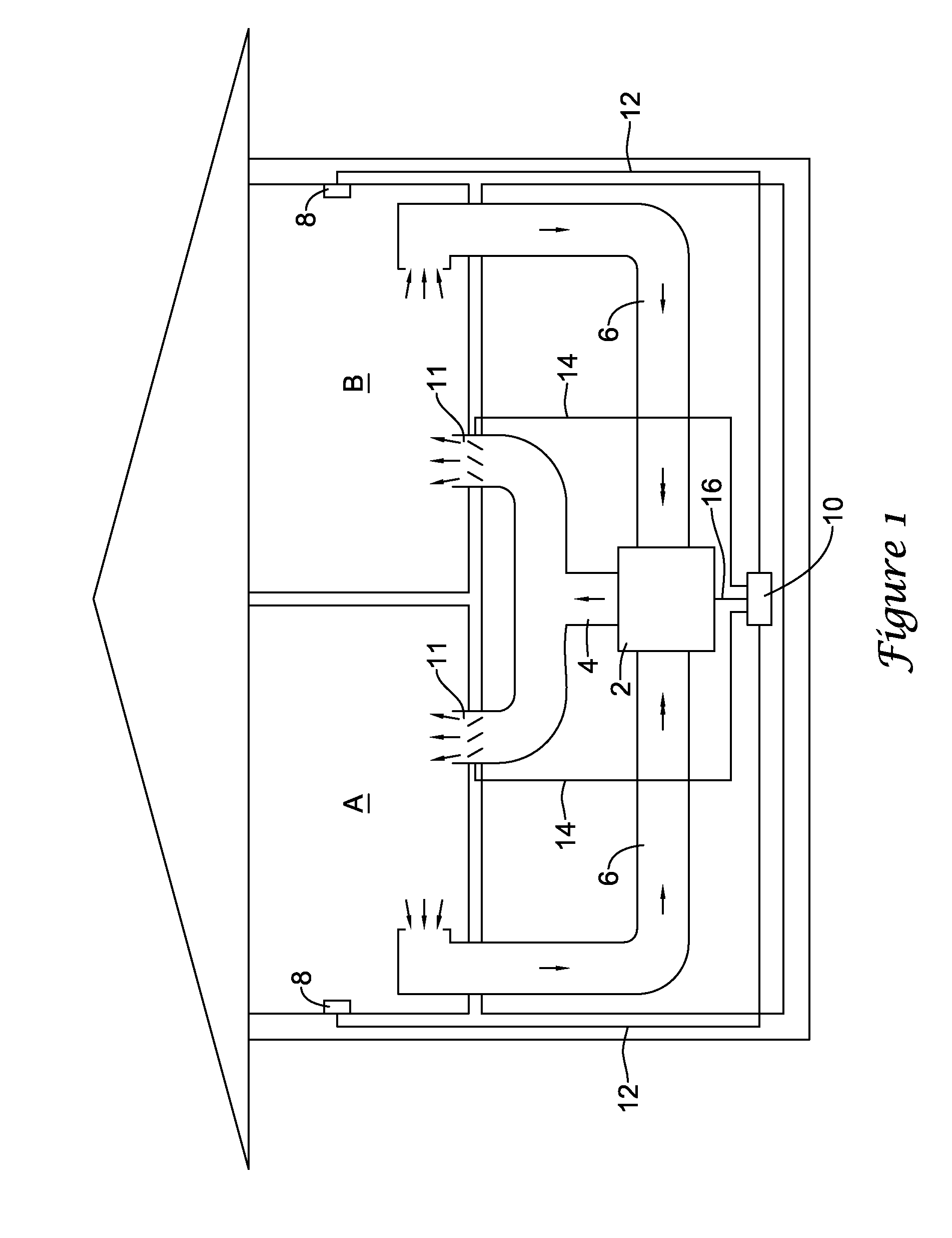
[0013]FIG. 1 is a schematic view of a building or other structure having an illustrative zoned heating, ventilation, and air conditioning (HVAC) system. While FIG. 1 shows a typical force air type HVAC system, other types of HVAC systems may be used including hydronic systems, boiler systems, radiant heating systems, electric heating systems, or any other suitable type of HVAC system, as desired. Additionally, while FIG. 1 shows a zoned HVAC system, it is contemplated that a non-zoned HVAC system may be used, as desired.

[0014]As illustrated, the zoned HVAC system of FIG. 1 includes one or more HVAC components 2, a system of vents or ductwork 4 and 6, one or more HVAC controllers 8, and one or more HVAC...


PUM


Abstract

An electrical terminal assembly for an HVAC device is disclosed. In one illustrative embodiment, the terminal assembly includes one or more quick-connect or screwless type terminal blocks mounted on a printed circuit board. The terminal assembly may also include one or more test pads electrically connected to the one or more quick-connect or screwless terminals via one or more traces on the printed circuit board. The one or more test pads may include a recessed portion.

Description

PRIORITY CLAIM[0001]This application is a continuation-in-part of U.S. application Ser. No. 11 / 618,378, filed Dec. 29, 2006.FIELD[0002]The present invention relates generally to heating, ventilation, and air conditioning (HVAC) systems, and more particularly, to electrical terminals for HVAC controllers and other devices.BACKGROUND[0003]Heating, ventilation, and / or air conditioning (HVAC) systems are often used to control the comfort level within a building or other structure. In many HVAC systems, one or more HVAC controllers may be configured to activate and deactivate one or more HVAC components of the HVAC system to affect and control one or more environmental conditions within the building. These environmental conditions can include, but are not limited to, temperature, humidity, and / or ventilation. In many cases, the controller of the HVAC controller may include, or have access to, one or more sensors, and may use sensed parameters provided by the one or more sensors to contro...

Claims


Application Information

Patent Timeline
Patent Type & Authority Patents(United States)
IPC IPC(8): H01R11/20
CPCH01R12/515H01R4/4836H01R2201/20Y10S439/912H01R4/48365
Inventor MULHOUSE, DAVID P.ZAVODNY, LUDEK
Owner ADEMCO INC
Why Eureka
Try Eureka