Engine arrangements and control

a technology for gas turbine engines and engine components, applied in the direction of engines/engines, mechanical equipment, engine components, etc., can solve the problems of imbalances within the engine, significant complicating the engine control, and introducing more fuel

Inactive Publication Date: 2010-01-19
ROLLS ROYCE PLC
View PDF8 Cites 18 Cited by
  • Summary
  • Abstract
  • Description
  • Claims
  • Application Information

AI Technical Summary

Benefits of technology

[0013]In accordance with certain aspects of the present invention there is provided a method of controlling a gas turbine engine comprising a number of compressor stages, the method comprising determining a parameter for each of a number of parts of the engine, comparing each parameter with a reference value...

Problems solved by technology

Such variations significantly complicate engine control.
Normally, an engine arrangement will incorporate several shafts and therefore when power is taken from one shaft to drive electrical generators/machines and other auxiliary devices imbalances may occur within the engine.
Recent requirements for the aerospace gas turbines to provide very large levels of core power to the aircraft electrical generators can cause problems.
For multi shaft engines being controlled to a constant thrust the drop in the working line of one of the compressors will result in more fuel being introduced and a ...

Method used


Image

  • Engine arrangements and control
  • Engine arrangements and control
  • Engine arrangements and control

Examples


first embodiment

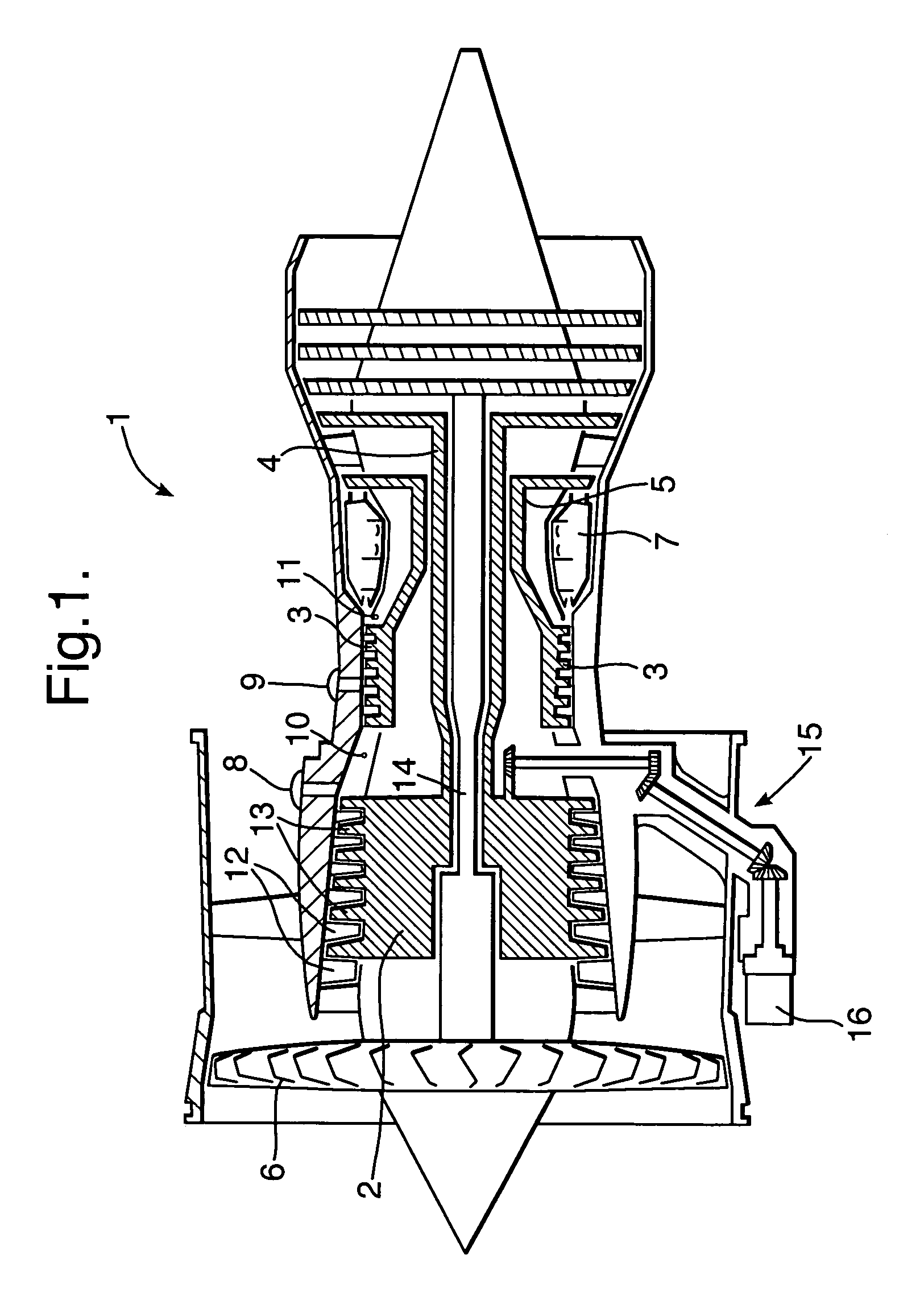
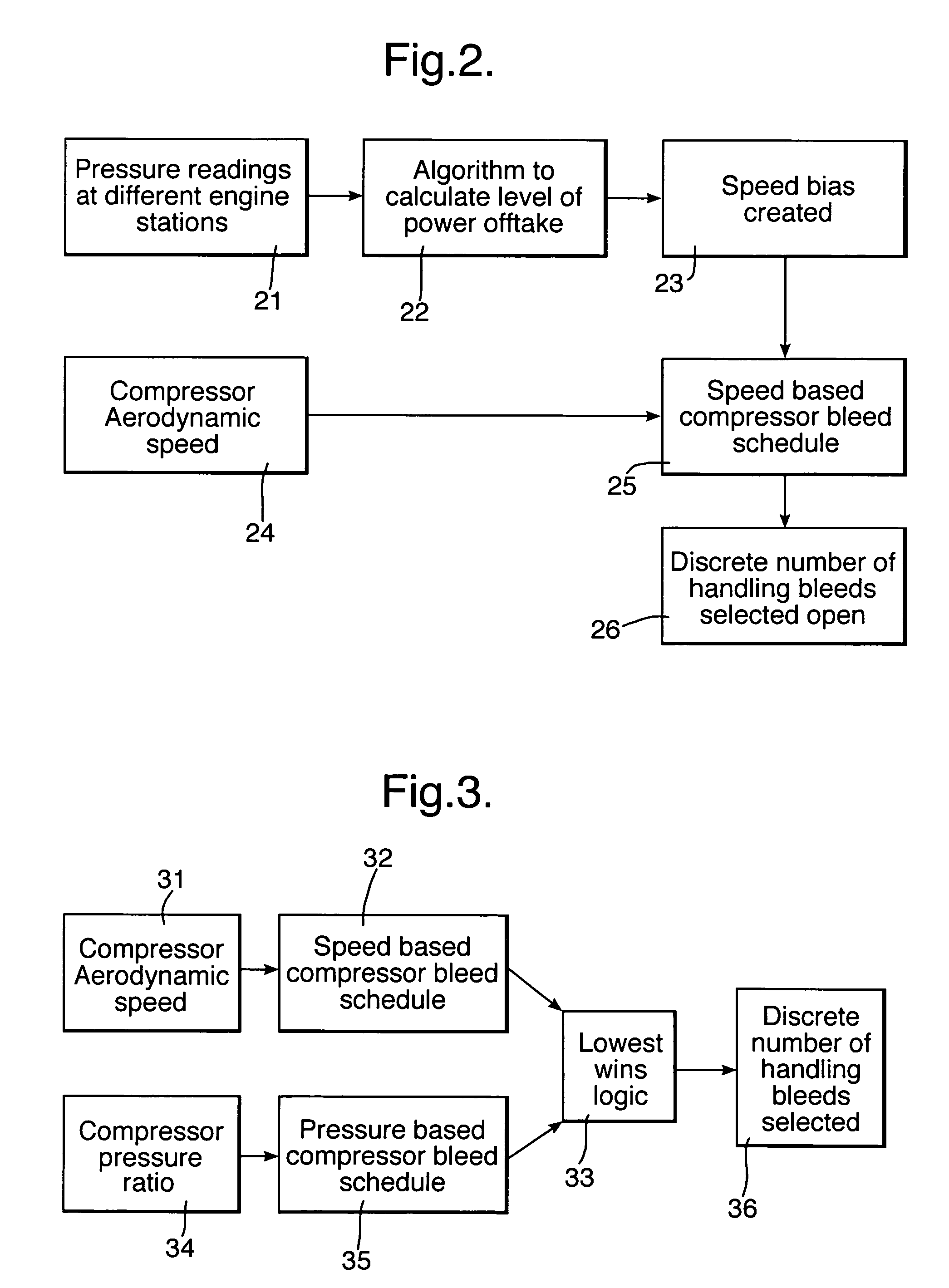
[0034]In a first embodiment in accordance with certain aspects of the present invention the amount of engine rematching is achieved by measuring parameters at different stations or ports (e.g. 11, 12) throughout the engine. These parameters can then be compared to reference values to determine the current level of power extraction. This knowledge can then be used to schedule appropriate opening of leakage bleed valves in the appropriate locations of the engine.

[0035]In a large three shaft turbofan, embodying power extraction from the intermediate pressure (IP) shaft traditional bleed scheduling would open IP handling bleed valves 8, 9 at idle powers because the intermediate pressure compressor surge margin was reduced. However, when high levels of power off take are being taken the intermediate pressure compression working line is much lower and this bleed is not required. In addition the large power off take means that the engine must rematch and the high pressure compressor operat...

second embodiment

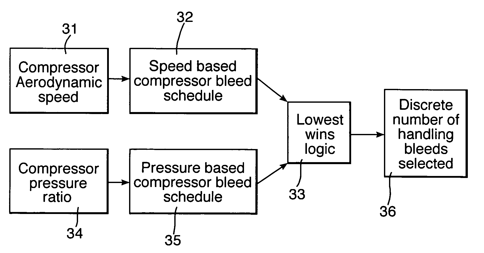
[0038]In a second embodiment in accordance with certain aspects of the present invention the effect of engine rematching is identified directly by changes in the compressor pressure ratios. These changes are then used to suitably schedule handling bleed by means of lowest wins logic between two competing bleed schedules. In this case the traditional bleed schedule based on corrected speed is used to protect the compressor surge margin under low power off take conditions. A second bleed schedule based on a suitable pressure ratio is used to protect the second compressor when it is affected by rematching caused by high power off take conditions.

[0039]With an engine arrangement this second engine control method is used to schedule operation of intermediate pressure handling bleed valves. A corrected speed schedule is used to protect the intermediate pressure compressor surge margin. In addition a high pressure compressor pressure ratio schedule is used to protect the high pressure comp...


PUM


Abstract

It is known that power is normally extracted within a gas turbine engine from a shaft in order to drive auxiliary devices such as electrical power generators. With high extraction rates from such shafts there is mismatching in rotational speeds between the shafts which must be adjusted through leakage taken from valves 8, 9. By measuring parameters and in particular pressure at a number of positions or parts within an engine arrangement 1 and comparing those parameters either through ratios or directly with reference values a controller can be configured in order to choose the correct sequence and scheduling of the valves 8, 9 opening to balance shaft speed. In such circumstances more efficient operation of the engine arrangement can be achieved over a wider range of engine speeds including idling.

Description

FIELD OF THE INVENTION[0001]The present invention relates to engine arrangements and control and more particularly to gas turbine engine arrangements and control with regard to aircraft propulsion.BACKGROUND OF THE INVENTION[0002]It will be understood that gas turbine engines are utilised with regard to aircraft in order to provide propulsion in order to drive the aircraft both on the ground as well as provide propulsion in the air. In such circumstances the power required will vary dependent upon the operational phase of the aircraft. It will also be understood that these gas turbine engines also provide power in order to drive electrical generators and other auxiliary devices such as hydraulic or fuel pumps for the aircraft and the engine itself. These generators and auxiliary devices are typically driven through a gear box drive coupling to a shaft of the engine.[0003]Increasing use of electrical actuators and devices to provide auxiliary functions as well as greater use of elect...

Claims


Application Information

Patent Timeline
IPC IPC(8): F02C9/18F02C7/32
CPCF02C9/18F05D2270/301F05D2270/70F05D2270/023F05D2270/06F05D2270/64
Inventor ZEWDE, NETSEBRAK TROWE, ARTHUR L
Owner ROLLS ROYCE PLC
Why Eureka
Try Eureka