
Highly efficient series string LED driver with individual LED control
a technology of led driver and led control, which is applied in the direction of electric variable regulation, process and machine control, instruments, etc., can solve the problems of low current flow through the other leds which are on and low power dissipation in the switch (current squared times resistance), and achieve high resistance in parallel, low resistance, and high resistance.
- Summary
- Abstract
- Description
- Claims
- Application Information
AI Technical Summary
Benefits of technology
Problems solved by technology
Method used
Image

Examples
Embodiment Construction
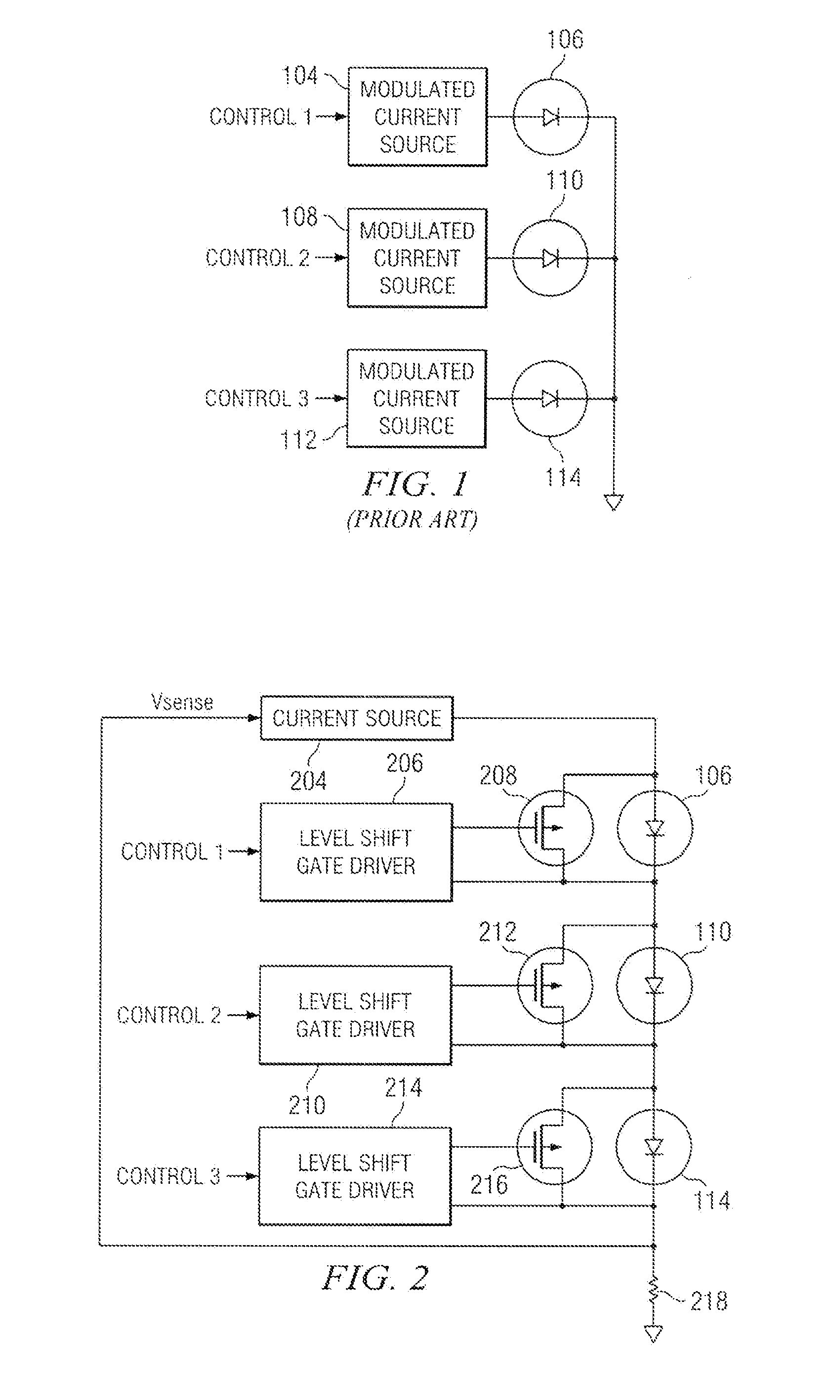
[0027]In FIG. 1 (prior art), a plurality of LEDs 106, 110, 114 each are driven by a MODULATED CURRENT SOURCE 104, 108, 112 respectively. A first terminal of MODULATED CURRENT SOURCE 104 is coupled to a first terminal of LED 106. A second terminal of LED 106 is coupled to ground. A first CONTROL 1 signal is coupled to a second terminal of MODULATED CURRENT SOURCE 104. In a similar fashion, a first terminal of MODULATED CURRENT SOURCE 108 is coupled to a first terminal of LED 110. A second terminal of LED 110 is coupled to ground. A second CONTROL 2 signal is coupled to a second terminal of MODULATED CURRENT SOURCE 108. A first terminal of MODULATED CURRENT SOURCE 112 is coupled to a first terminal of LED 114. A second terminal of LED 114 is coupled to ground. A third CONTROL 3 signal is coupled to a second terminal of MODULATED CURRENT SOURCE 112.
[0028]In operation, current from MODULATED CURRENT SOURCE 104 flows through LED 106 and then to ground, causing LED 106 to generate light w...
PUM
 Abstract
Description
Claims
Application Information