Integrity testable multilayered filter device

a filter device and multi-layer technology, applied in the field of integration testable multi-layer filter devices, can solve the problems of one layer not providing a conclusive indication of a defect, a filter or its sealing into the device,

Inactive Publication Date: 2010-01-26
MILLIPORE CORP
View PDF12 Cites 39 Cited by
  • Summary
  • Abstract
  • Description
  • Claims
  • Application Information

AI Technical Summary

Problems solved by technology

If the flow increase downstream is too quick or at a low pressure, this indicates that there is a defect in the filter or its sealing into the device.
The problem with using this test in devices with multiple layers of membrane is that only the overall device is tested and the test can only indicate if there is a defect in all the layers.
A defect in one layer may not provide one with a conclusive indication of a defect.

Method used


Image

  • Integrity testable multilayered filter device
  • Integrity testable multilayered filter device
  • Integrity testable multilayered filter device

Examples


example

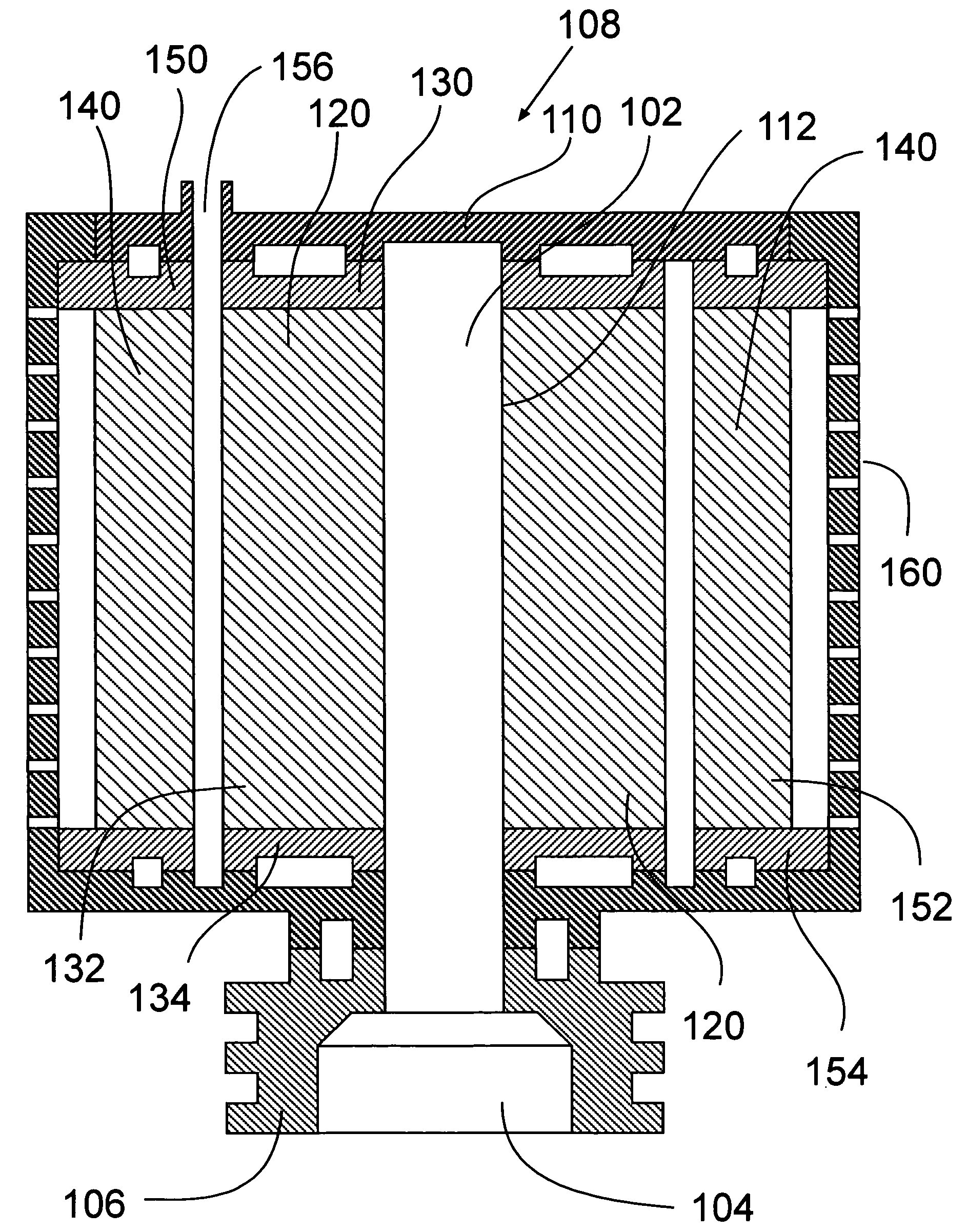
[0057]A device made according to the embodiment of FIG. 3 using a PES ultrafiltration membrane available from Millipore Corporation was made.

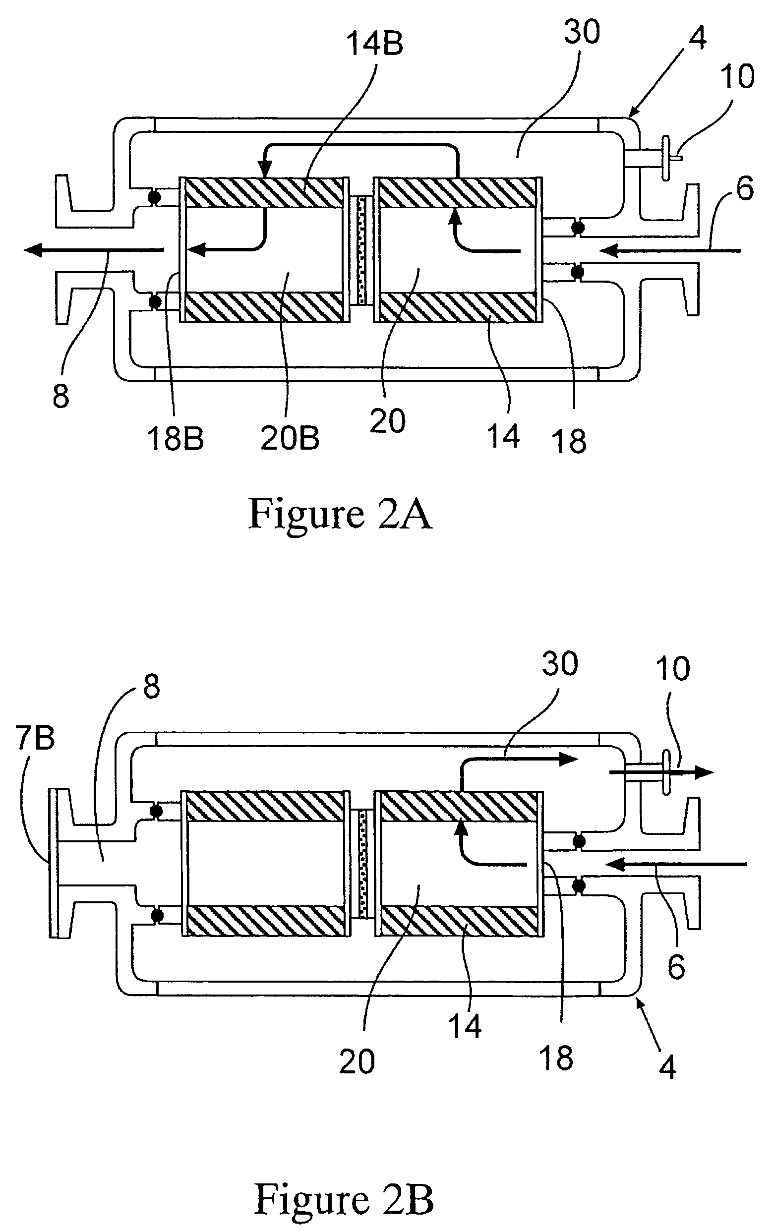
[0058]Both top and bottom layers of membrane were wet with water, the port was opened and the outlet was closed by inserting a plug. Air at 75 psi was flowed through the inlet to the filter layer and a flow meter that was positioned downstream of the port to read the flow. The results were <0.01 cc / min.

[0059]To test the second layer, the port was opened and the inlet was closed by inserting a plug. Air at 75 psi was flowed through the outlet to the filter layer and a flow meter that was positioned downstream of the port to read the flow. The results were <0.01 cc / min.

[0060]The recommended value for the membranes as supplied by the vendor was <0.01 cc / min. As the measured value for each layer was within this range, each layer and the device as a whole was determined to be integral.


PUM

PropertyMeasurementUnit
molecular weightaaaaaaaaaa
defectaaaaaaaaaa
hydrophilicaaaaaaaaaa

Abstract

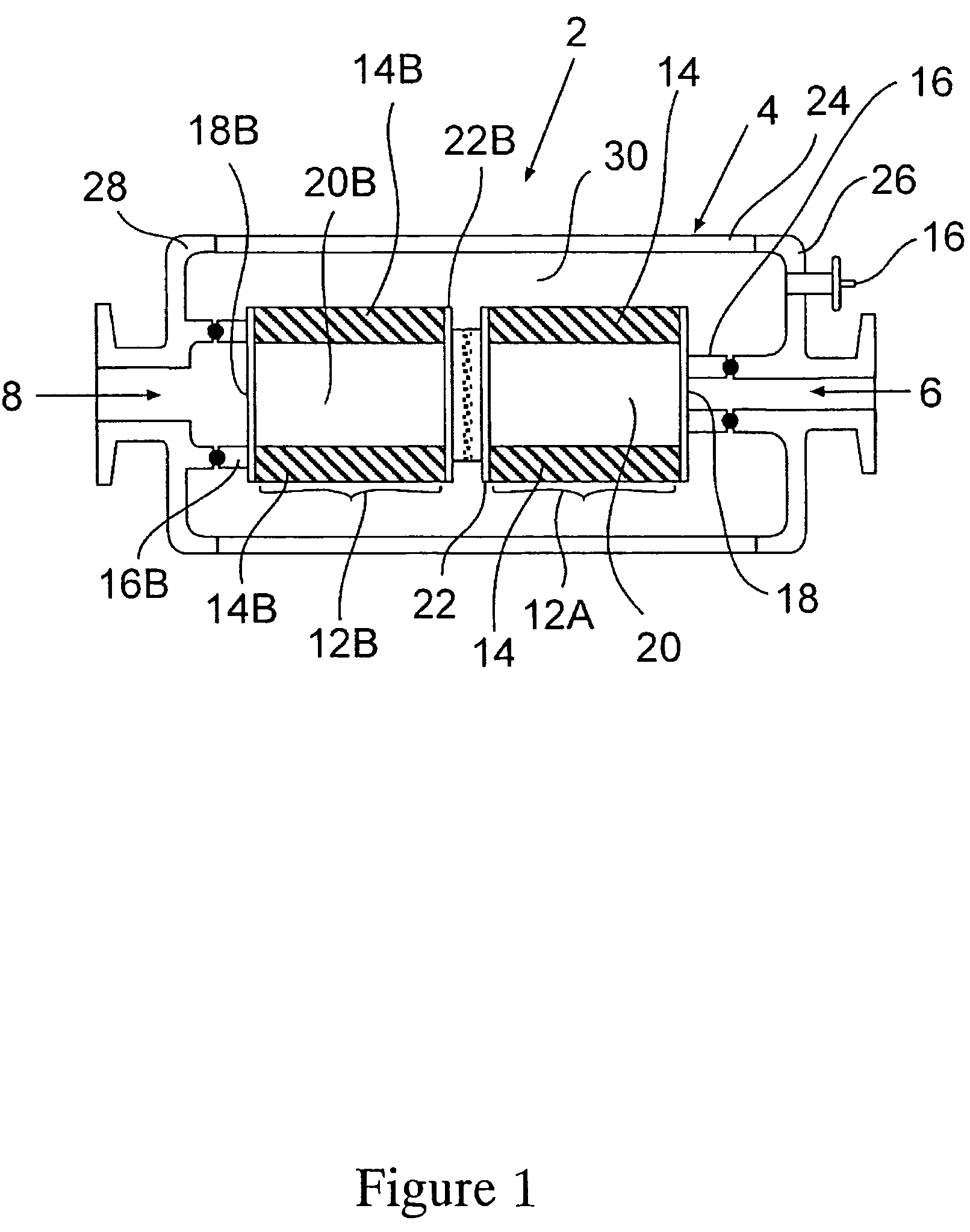
The present invention comprises a filter housing having two or more layers of filters. Each layer is preferably spaced apart from each other so as to provide a chamber or gap between them. A port or vent is located within the chamber or gap between the two layers to provide an intermediate path for gas or liquid to flow through one layer of filter or membrane and out the vent or port for integrity testing.

Description

CROSS REFERENCE TO RELATED APPLICATIONS[0001]The present utility patent application claims the benefit of U.S. Provisional Patent Application No. 60 / 725,423, filed on Oct. 11, 2005 and U.S. Provisional Patent Application No. 60 / 728,914, filed on Oct. 21, 2005. The entire contents of which are incorporated herewith in entirety.[0002]The present invention relates to a device containing multiple layers of filters or membrane that is capable of being integrity tested. More particularly, it relates to a device containing multiple layers of filters or membrane, each of which is capable of being integrity tested individually within an assembled device.BACKGROUND OF THE INVENTION[0003]Some filter devices contain two or more layers of membrane sandwiched together in order to gain certain performance characteristics such as retention. It is important that each layer remain integral and defect free throughout the assembly process and during its use.[0004]Normally integrity testing is done to t...

Claims


Application Information

Patent Timeline
Patent Type & Authority Patents(United States)
IPC IPC(8): G01N19/00
CPCB01D29/21B01D46/0023B01D63/082B01D65/102B01D63/14B01D29/232B01D29/58B01D2273/10B01D2319/022B01D2273/18B01D2313/90B01D46/62B01D2313/903
Inventor NAUSEDA, CURTISBACKES, KARIRAUTIO, KEVIN
Owner MILLIPORE CORP
Why Eureka
Try Eureka