
Apparatus and methods for imaging and attenuation correction

a technology of attenuation correction and apparatus, applied in the field of nuclear radiation imaging integration, can solve the problems of affecting the clinical potential of radionuclide imaging, the functional image may not show structural details, and the image fusion may be somewhat erroneous,

Inactive Publication Date: 2010-01-26
SPECTRUM DYNAMICS MEDICAL LTD
View PDF199 Cites 114 Cited by
  • Summary
  • Abstract
  • Description
  • Claims
  • Application Information

AI Technical Summary

Problems solved by technology

However, a functional image may not show structural details.
However, when raw radioactive emission data is superimposed on a structural image, the resultant image fusion may be somewhat erroneous, due to tissue attenuation.
The full clinical potential of radionuclide imaging has been seriously hindered by some important limitations.
The spatial resolution and photon statistical limitations of radionuclide imaging frustrate accurate anatomical localization and hinder quantitation of the radionuclide distribution.
Photon attenuation has been identified by the American Heart Association and leading nuclear cardiologists as a major deficiency in diagnosis of heart disease with SPECT, and is a major source of error in the measurement of tumor metabolism using radionuclide techniques.
Quantitation is further complicated by the need for scatter compensation for imaging with both single-photon and positron-emitting radionuclides.
Existing medical imaging instrumentation has been designed for either emission or transmission imaging, but not both, and attempts to perform both compromise one or both of the data sets.
In addition, in the early 1990's when much of this work was done, implementation of iterative reconstruction algorithms was too slow to converge and therefore impeded the flow of information in a hospital setting.
The efficiency of analytic approaches is compromised by their inability to account for the quantitative errors of photon attenuation, scatter radiation, and spatial resolution losses mentioned above.
However, these approaches are computationally intensive, require that the patient be scanned separately on two systems, and have only been successful in the head where the skull limits motion of internal anatomical structures.
However, they are inexact and utilize a uniform attenuation map in which the value of the attenuation coefficient is assumed to be constant across the patient.
The major disadvantage of iterative algorithms is their computational burden, which when introduced, in the early 1990's represented a major obstacle.
Unfortunately it is generally not possible to modify filtered backprojection algorithms to accurately account for details of the collimator geometry, or for the effects of scatter, especially in regions where there are large inhomogeneities in these properties, or details of the collimator geometry.
However, all iterative reconstruction methods require significantly more computer time than filtered backprojection algorithms to generate useful images.
The requirement to acquire complete sets of projection data is especially important in radionuclide system because clinical emission imaging systems typically require several minutes to acquire projection data, making iterative reconstruction techniques impractical.
However, the aforementioned patents and publications suffer from a basic drawback.
Therefore liver scans, for instance, did not show possible carcinomas or other pathological states.
This environment can result in deficient images because the various orientations of the RF coil, e.g., in an artery, will not be positioned always colinearly with the RF excitation field.

Method used


Image

  • Apparatus and methods for imaging and attenuation correction
  • Apparatus and methods for imaging and attenuation correction
  • Apparatus and methods for imaging and attenuation correction

Examples


example 1

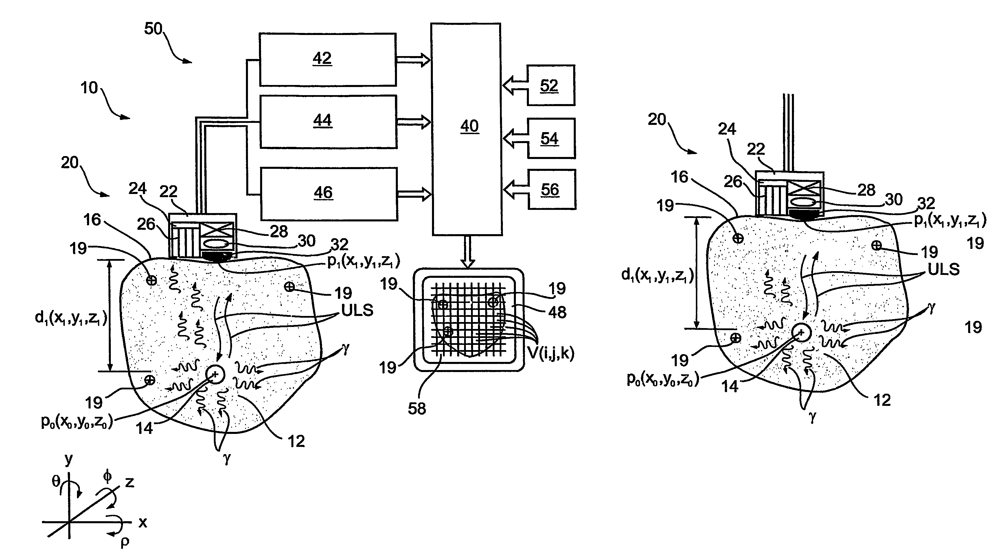
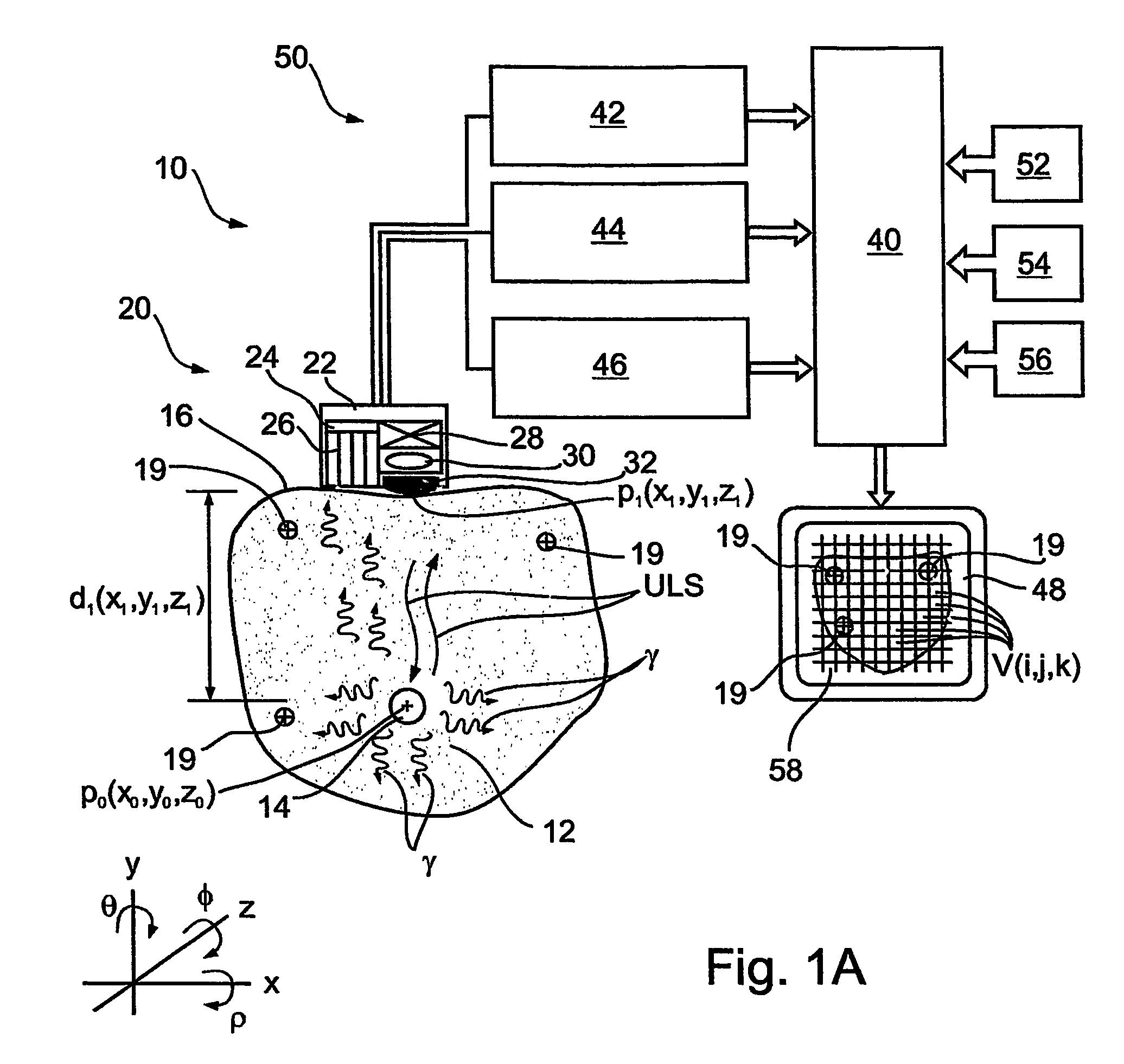
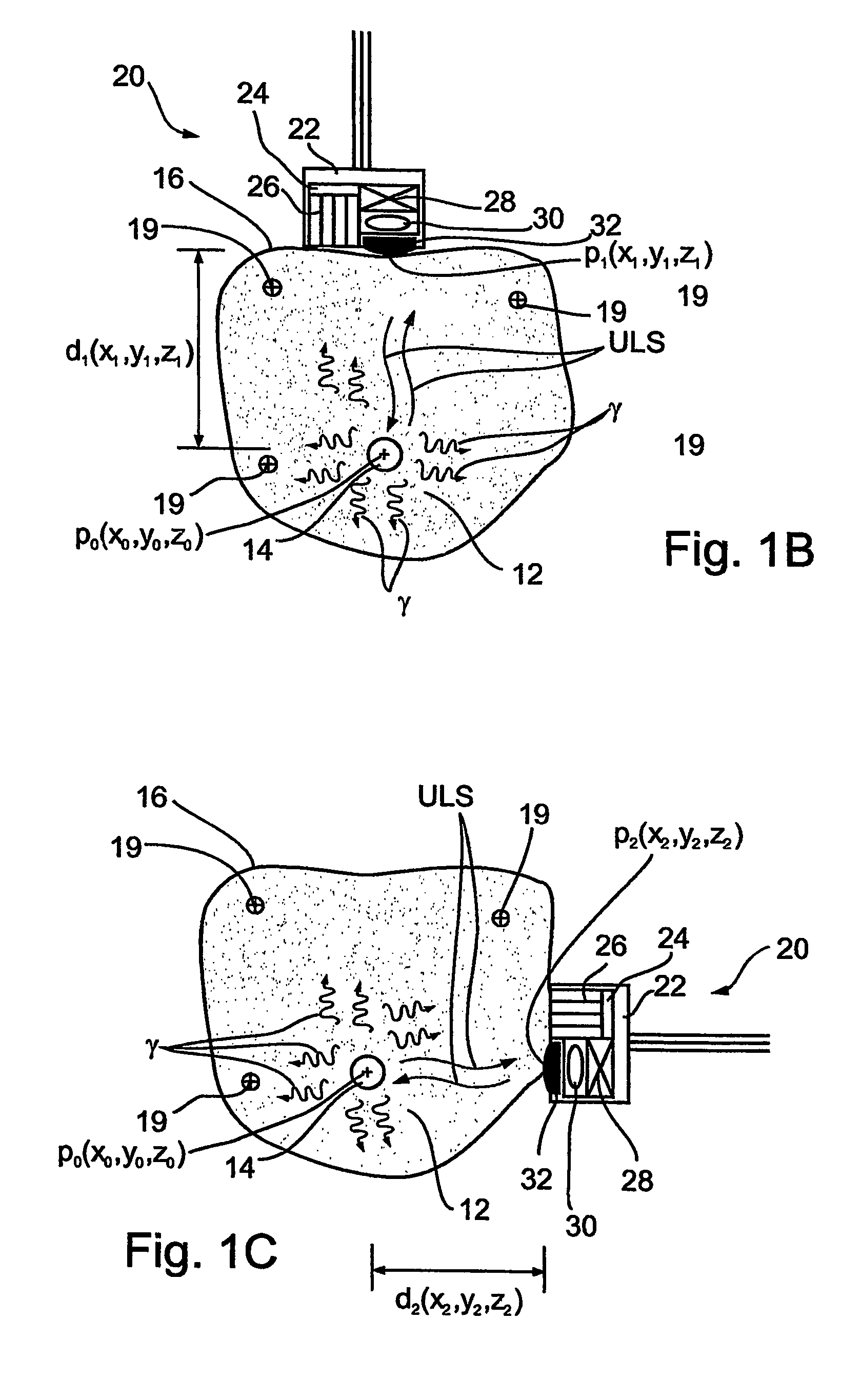
[0256]Referring further to the drawings, FIGS. 4A-4E schematically illustrate a handheld system 100 for simultaneous nuclear-radiation and ultrasound imaging, in accordance with the present invention, as taught in conjunction with FIG. 1A, hereinabove.

[0257]Handheld system 100 is adapted to perform freehand, extracorporeal scanning by nuclear radiation and ultrasound, simultaneously. Additionally, computer system 50 (FIG. 1A) is adapted to receive input from handheld system 100 and provide an attenuation-corrected nuclear-radiation image as well as a superposition of the attenuation-corrected nuclear-radiation image and the ultrasound image, for example, on display screen 48. Furthermore, handheld system 100 may be operative to guide an in-vivo instrument tip 25 (FIG. 1H) based on the superposition of the attenuation-corrected nuclear-radiation image and the ultrasound image, for example, as seen on display screen 48 (FIG. 1H).

[0258]As seen in FIG. 4A, handheld system 100 preferably...

example 2

[0273]Referring further to the drawings, FIGS. 4F-4J schematically illustrate a handheld system 140 for simultaneous nuclear-radiation and ultrasound imaging, in accordance with the present invention, as taught in conjunction with FIG. 2A, hereinabove.

[0274]System 140 is analogous to system 70 of FIG. 2A. Thus, two separate handheld probes: probe 72 for nuclear radiation imaging and probe 76 for ultrasound are used, both having substantially identical position registering devices 30A and 30B. The manner of using system 140 is similar to that of using system 100, however, in place of simultaneous scanning, for nuclear radiation and ultrasound, each is performed individually, and computer system 50 combines the results.

[0275]Thus, handheld system 140 is adapted to perform freehand, extracorporeal scanning by nuclear radiation and ultrasound. Additionally, computer system 50 (FIG. 2A) is adapted to receive input from handheld system 140 and provide an attenuation-corrected nuclear-radi...

example 3

[0279]Referring further to the drawings, FIGS. 5A and 5E schematically illustrate a rectal probe 200 for simultaneous nuclear-radiation and ultrasound imaging, in accordance with the present invention, as taught in conjunction with FIG. 1A, hereinabove.

[0280]Rectal probe 200 is adapted to perform intracorporeal scanning of the rectum by nuclear radiation and ultrasound, simultaneously. Additionally, computer system 50 (FIG. 1A) is adapted to receive input from rectal probe 200 and provide an attenuation-corrected nuclear-radiation image as well as a superposition of the attenuation-corrected nuclear-radiation image and the ultrasound image, for example, on display screen 48. Furthermore, rectal probe 200 may be operative for focused ablation, for example, of a tumor, based on the superposition of the attenuation-corrected nuclear-radiation image and the ultrasound image.

[0281]As seen in FIGS. 5A-5B, rectal probe 200 includes an intracorporeal portion 112, for insertion to the rectum...


PUM


Abstract

Imaging apparatus, is provided, comprising a first device, for obtaining a first image, by a first modality, selected from the group consisting of SPECT, PET, CT, an extracorporeal gamma scan, an extracorporeal beta scan, x-rays, an intracorporeal gamma scan, an intracorporeal beta scan, an intravascular gamma scan, an intravascular beta scan, and a combination thereof, and a second device, for obtaining a second, structural image, by a second modality, selected from the group consisting of a three-dimensional ultrasound, an MRI operative by an internal magnetic field, an extracorporeal ultrasound, an extracorporeal MRI operative by an external magnetic field, an intracorporeal ultrasound, an intracorporeal MRI operative by an external magnetic field, an intravascular ultrasound, and a combination thereof, and wherein the apparatus further includes a computerized system, configured to construct an attenuation map, for the first image, based on the second, structural image. Additionally, the computerized system is configured to display an attenuation-corrected first image as well as a superposition of the attenuation-corrected first image and the second, structural image. Furthermore, the apparatus is operative to guide an in-vivo instrument based on the superposition.

Description

CROSS REFERENCE TO RELATED PATENT APPLICATIONS[0001]This application is a National Phase Application of PCT / IL03 / 00917 having International Filing Date of 4 Nov. 2003, which claims benefit of from U.S. Provisional Patent Application No. 60 / 423,359 filed 4 Nov. 2002, and from U.S. patent application Ser. No. 10 / 616,307 filed 10 Jul. 2003, and from U.S. patent application Ser. No. 10 / 616,301 filed 10 Jul. 2003.FIELD AND BACKGROUND OF THE INVENTION[0002]The present invention relates to the integration of nuclear-radiation imaging, on the one hand, with ultrasound or magnetic resonance imaging, on the other, in order to superimpose the two images, and in order to utilize the structural information of the ultrasound or magnetic resonance for attenuation correction of the nuclear-radiation image.[0003]In essence, two types of medical images may be distinguished:[0004]1. functional body images, such as may be produced by gamma camera, SPECT, and PET scans, which provide physiological infor...

Claims


Application Information

Patent Timeline
Patent Type & Authority Patents(United States)
IPC IPC(8): G01T1/24A61B5/05A61B1/05A61B1/31A61B5/055A61B5/06A61B6/00A61B8/00A61B19/00A61N7/02G06T5/50G06T7/00
CPCA61B1/05A61B34/20A61B5/06A61B6/037A61B6/482A61B6/5247A61B8/5238G01R33/481G06T5/50A61B6/4417A61B8/00A61B8/4472A61N7/02G06T2207/10081G06T2207/10088G06T2207/10132G06T2207/30004A61B1/0005A61B2034/2072A61B34/25A61B2090/364A61B2034/2051A61B2090/378A61B2090/365A61B1/31G01T1/1603
Inventor KIMCHY, YOAVAMRAMI, RONIZILBERSTEIN, YOEL
Owner SPECTRUM DYNAMICS MEDICAL LTD
Learn More