Backlit static display on foam board using light piping pegs as highlighters

a static display and foam board technology, applied in the field of backlit static display, can solve the problems of limited patterns, lack of user experience, and inability to superimpose images,

Inactive Publication Date: 2010-02-02
PETERS MARK +1
View PDF27 Cites 18 Cited by
  • Summary
  • Abstract
  • Description
  • Claims
  • Application Information

AI Technical Summary

Benefits of technology

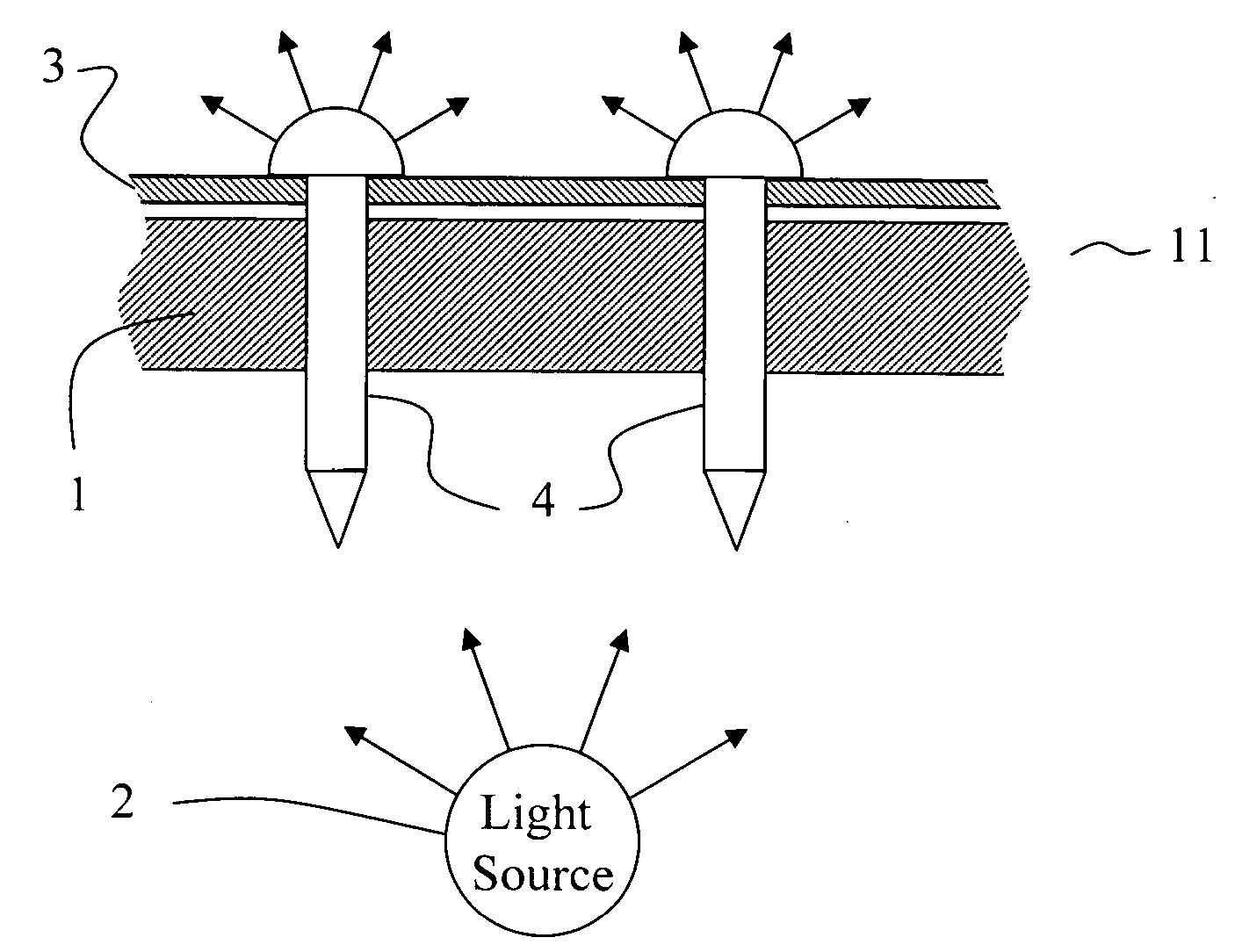
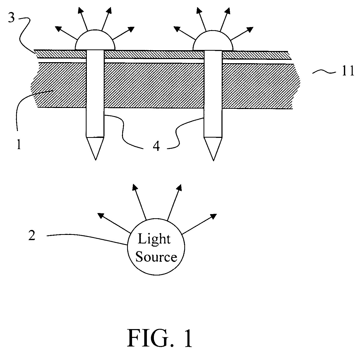
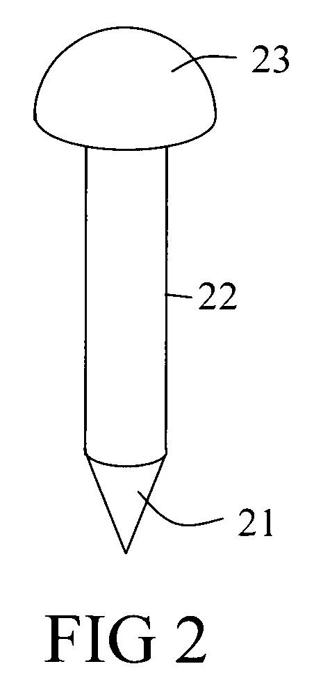
[0021]e) a plurality of pegs equal in number to the number of holes. The pegs are longer than the thickness of the display cover and furthermore are significantly more translucent than the display cover, such that when inserted through the display cover, they operate as light pipes. They channel light generated by the light source, across the display cover, and scatter light toward the viewer, thereby allowing the pegs to operate as highlighters.

Problems solved by technology

While useful, devices as described in the prior art do not offer the opportunity for highlighting locations of interest by allowing the user or viewer to increase or decrease at will the transparency of the slide at those locations.
These patterns however, are limited to the discrete combinations of peg placements in the regularly spaced holes.
In addition, this device does not give the user the opportunity to superimpose an image on the light pattern generated by the pegs.

Method used


Image

  • Backlit static display on foam board using light piping pegs as highlighters
  • Backlit static display on foam board using light piping pegs as highlighters
  • Backlit static display on foam board using light piping pegs as highlighters

Examples


Embodiment Construction

[0023]As required, detailed embodiments of the present invention are disclosed herein; however, it is to be understood that the disclosed embodiments are merely exemplary of the invention which may be embodied in various forms. Therefore, specific structural and functional details disclosed herein are not to be interpreted as limiting, but merely as a basis for the claims and as a representative basis for teaching one skilled in the art to variously employ the present invention in virtually any appropriately detailed structure.

[0024]Reference is now made to the drawings, wherein like characteristics and features of the present invention shown in the various figures are designated by the same reference numerals.

[0025]FIG. 1 illustrates the basic concept in this invention. A layer 1 of “punchable” material such as a foam board is placed above a source of light 2 which shall be referred to as a back light. The definition of “punchable” layer shall be provided in the next paragraph. An ...


PUM


Abstract

A display for displaying an image to a viewer, capable of highlighting specific locations selected by a user. This display comprises:a) a punchable layer such as a foam board having a first surface and a second surface,b) an image affixed to the first surface of the punchable layer. The punchable layer and the image form a sandwich dubbed display cover which is partially transparent and is observed by a viewer located on the image side of the display cover,c) a light source illuminating the second surface of the punchable layer,d) a piercing means for enabling the user to punch at least one hole into the punchable layer, ande) a plurality of pegs equal in number to the number of holes. The pegs are longer than the thickness of the display cover and furthermore are significantly more translucent than the display cover, such that when inserted into the holes by the user, they operate as light pipes and channel light generated by the light source, across the display cover, and scatter light toward the viewer, thereby allowing the pegs to operate as highlighters over the lesser illuminated display cover.

Description

FIELD OF THE INVENTION[0001]The present invention relates to light displays, more precisely, back-lit static slide displays in which most of the display is opaque or slightly translucent, while small selected areas are made extremely luminous by the insertion of translucent pegs that act as light pipes and allow the back light to channel through them, making them highly visible.BACKGROUND[0002]Backlit static displays are well known devices that have been used in a wide diversity of applications. These devices, which typically comprise a translucent slide placed in front of a light source, provide a uniform rendition of the image on the slide. While useful, devices as described in the prior art do not offer the opportunity for highlighting locations of interest by allowing the user or viewer to increase or decrease at will the transparency of the slide at those locations.[0003]A device capable of displaying a backlit image with a controllable degree of transparency is described in U....

Claims


Application Information

Patent Timeline
Patent Type & Authority Patents(United States)
IPC IPC(8): G09F13/00
CPCG09F9/305
Inventor PETERS, MARKPETERS, LISA
Owner PETERS MARK
Why Eureka
Try Eureka