Panoramic camera mount

a technology for panoramic cameras and mounts, applied in the field of panoramic camera mounts, can solve the problems of difficult task, especially difficult task, and difficulty in properly aligning film strips or digital images to produce a panoramic pictur

Active Publication Date: 2010-02-09
REALLY RIGHT STUFF
View PDF55 Cites 66 Cited by
  • Summary
  • Abstract
  • Description
  • Claims
  • Application Information

AI Technical Summary

Problems solved by technology

Properly aligning film strips or digital images to produce a panoramic picture can be a difficult task.
This task is especially difficult if the camera is not properly centered on a rotatable mount.

Method used


Image

  • Panoramic camera mount
  • Panoramic camera mount
  • Panoramic camera mount

Examples


Embodiment Construction

[0023]For a vertical column of overlapping images, a panning clamp should have a vertical orientation. One technique to achieve this orientation is to mount a panning clamp on top of a tripod head or otherwise directly to a tripod. To more effectively use the panning clamp, the camera and lens should be mounted so that the camera and lens pivot around the nodal point or the entrance pupil. In most cases, this involves the camera and lens being backed off from the typical tripod mounting point so that the entrance pupil is located at the pivot point.

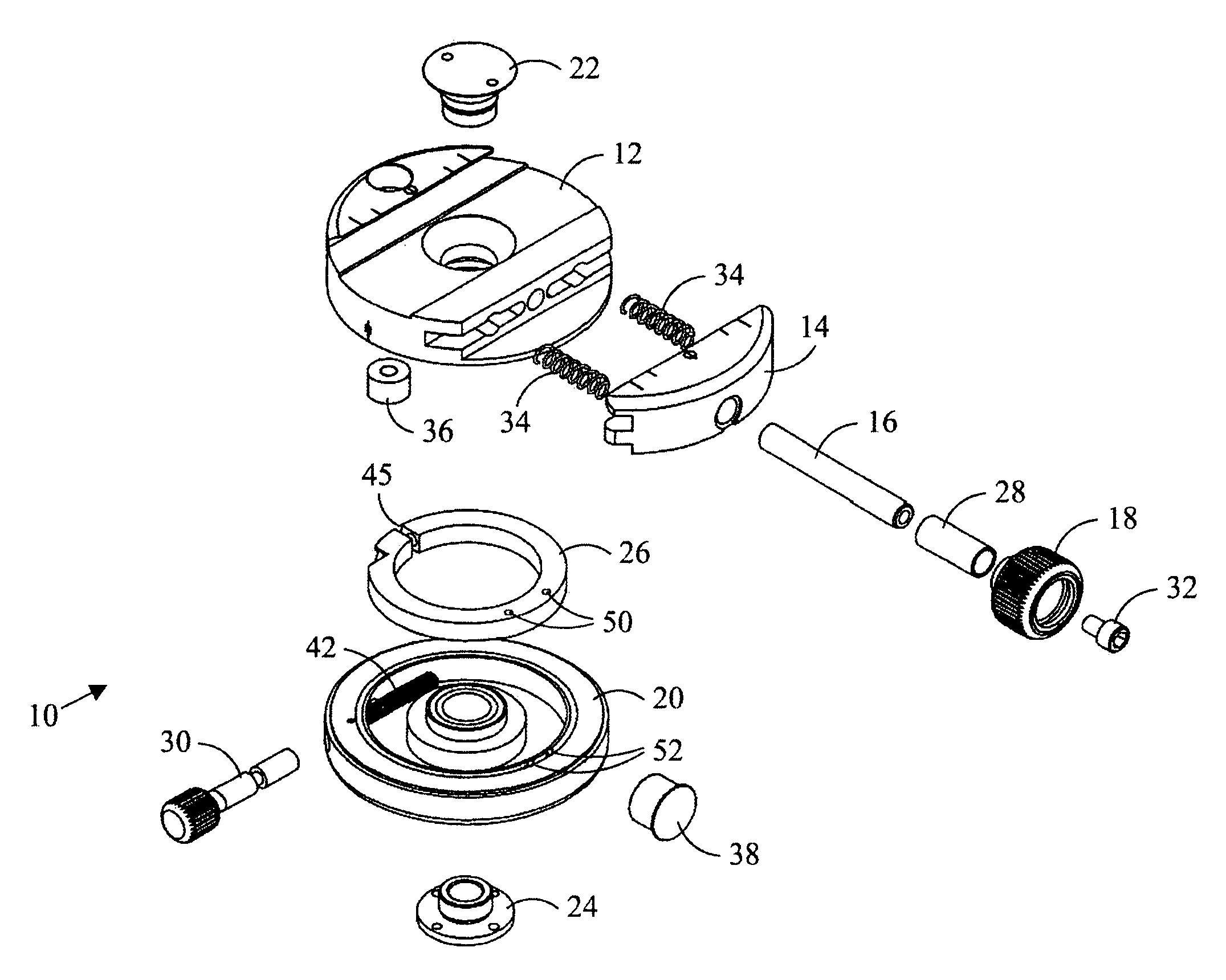
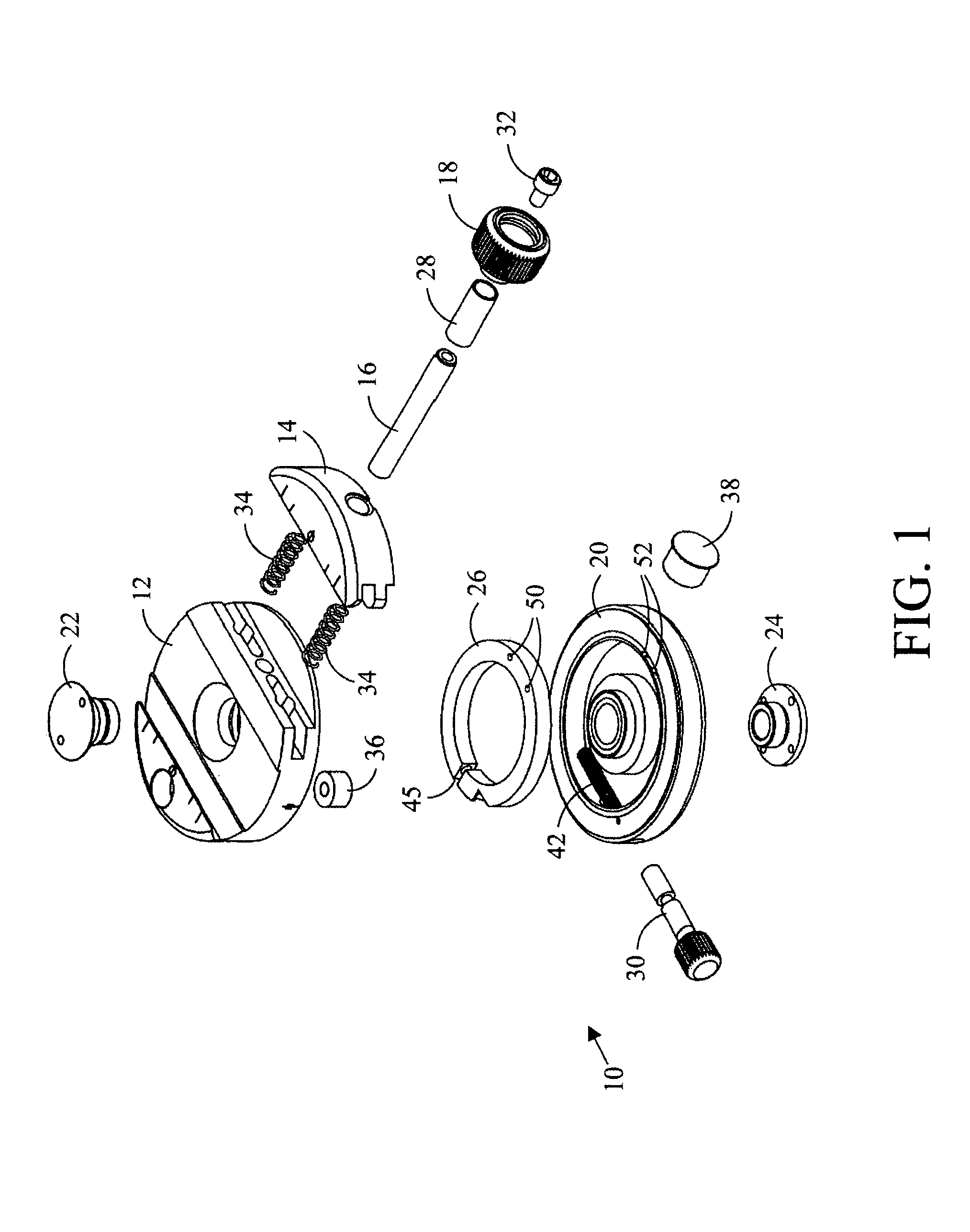
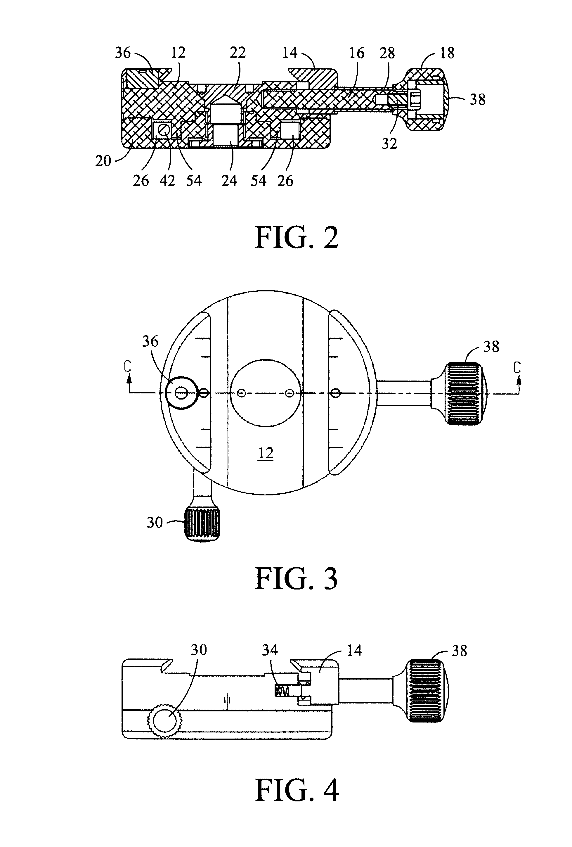
[0024]Referring to FIG. 1, a panning clamp 10 includes a clamp body 12 and a clamp jaw 14. The clamp jaw 14 is engaged with the body 12 by a pair of clamp springs 34. The springs 34 exert an outwardly directed force on the clamp jaw 14. The clamp jaw 14 is secured in place by the combination of a clamp screw 16, a clamp sleeve 28 surrounding the clamp screw 16, a clamp knob 18, and a screw 32. The clamp sleeve 28 sets the spacing for the ...


PUM


Abstract

A panoramic device includes a base member having a flat lower surface suitable to be supported by a tripod. A clamp member has a flat upper surface rotatably interconnected within a single plane of rotation with the base that includes a first rotatable knob to selectively inhibit the rotation of the clamp member with respect to the base. The flat upper surface includes a central region that is at a different elevation than another portion of the flat upper surface. The clamp includes a pair of opposed surfaces suitable to detachably secure a camera thereto. The one of the opposed surfaces is maintained in a fixed relationship with respect to the clamp member. The other one of the opposed surfaces is in a movable relationship with respect to the clamp member using a second rotatable knob. The first knob and the second knob are rotatably connected with respect to one another. The panoramic device includes a level bubble visible on an upper surface at a location exterior to the central region of the clamp.

Description

CROSS-REFERENCE TO RELATED APPLICATIONS[0001]This application claims the benefit of U.S. Provisional App. No. 60 / 642,045, filed Jan. 7, 2005.BACKGROUND OF THE INVENTION[0002]The present invention generally relates to a camera mount, and in particular to a camera mount suitable for taking panoramic pictures.[0003]Aberrations and distortions occur at the edge regions of a wide-angle view of a landscape. Taking and assembling together multiple images across the view results in a panoramic that is larger than is generally available using a single shot picture. Properly aligning film strips or digital images to produce a panoramic picture can be a difficult task. This task is especially difficult if the camera is not properly centered on a rotatable mount.[0004]A panoramic camera is disclosed in Gasso et al., U.S. Pat. No. 2,111,854, that includes an adjustable lens to vary the focal length of the lenses in mathematical proportions to the varying distances of objects in the panoramic vie...

Claims


Application Information

Patent Timeline
Patent Type & Authority Patents(United States)
IPC IPC(8): G03B17/00F16M11/02G03B21/00F16M11/04
CPCF16M11/02F16M11/04F16M11/041F16M11/08F16M11/16F16B2/065G03B17/56G03B37/00G03B17/561F16M11/2078G03B17/566F16M2200/027
Inventor JOHNSON, JOSEPH
Owner REALLY RIGHT STUFF
Why Eureka
Try Eureka