Anterior cervical plating system

a cervical plate and anterior cervical technology, applied in the field of spinal fusion systems, can solve the problems of only having one degree of freedom in the locking mechanism and not being able to provide pressure on the bone screw

Active Publication Date: 2010-02-16
ORTHOFIX US LLC
View PDF18 Cites 53 Cited by
  • Summary
  • Abstract
  • Description
  • Claims
  • Application Information

AI Technical Summary

Problems solved by technology

Of note, however, in these last two aforementioned systems it appears that each of the locking mechanisms is provided with only one degree of freedom, such that the locking mechanism may slide relative to the bone plate but may not be moved up or down relative to the bone plate (and relative to the bone screws within the bone plate).
Thus, these last two aforementioned systems do not appear capable of providing pressure on bone screws which are disposed at varying depths relative to the bone plate.

Method used


Image

  • Anterior cervical plating system
  • Anterior cervical plating system
  • Anterior cervical plating system

Examples


Embodiment Construction

[0015]Detailed embodiments of the present invention are disclosed herein; however, it is to be understood that the disclosed embodiments are merely illustrative of the invention that may be embodied in various forms. In addition, each of the examples given in connection with the various embodiments of the invention are intended to be illustrative, and not restrictive. Further, all of the measurements provided in the drawings are intended to be illustrative and not restrictive. Further still, the figures are not necessarily to scale, some features may be exaggerated to show details of particular components. Therefore, specific structural and functional details disclosed herein are not to be interpreted as limiting, but merely as a representative basis for teaching one skilled in the art to variously employ the present invention.

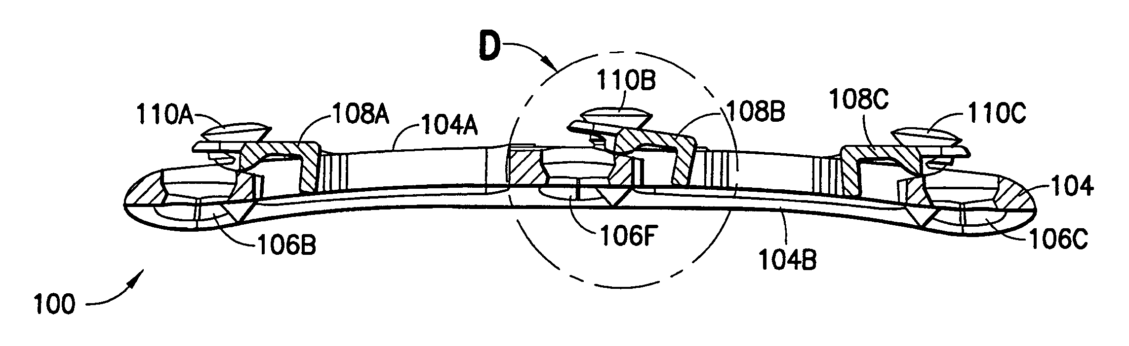
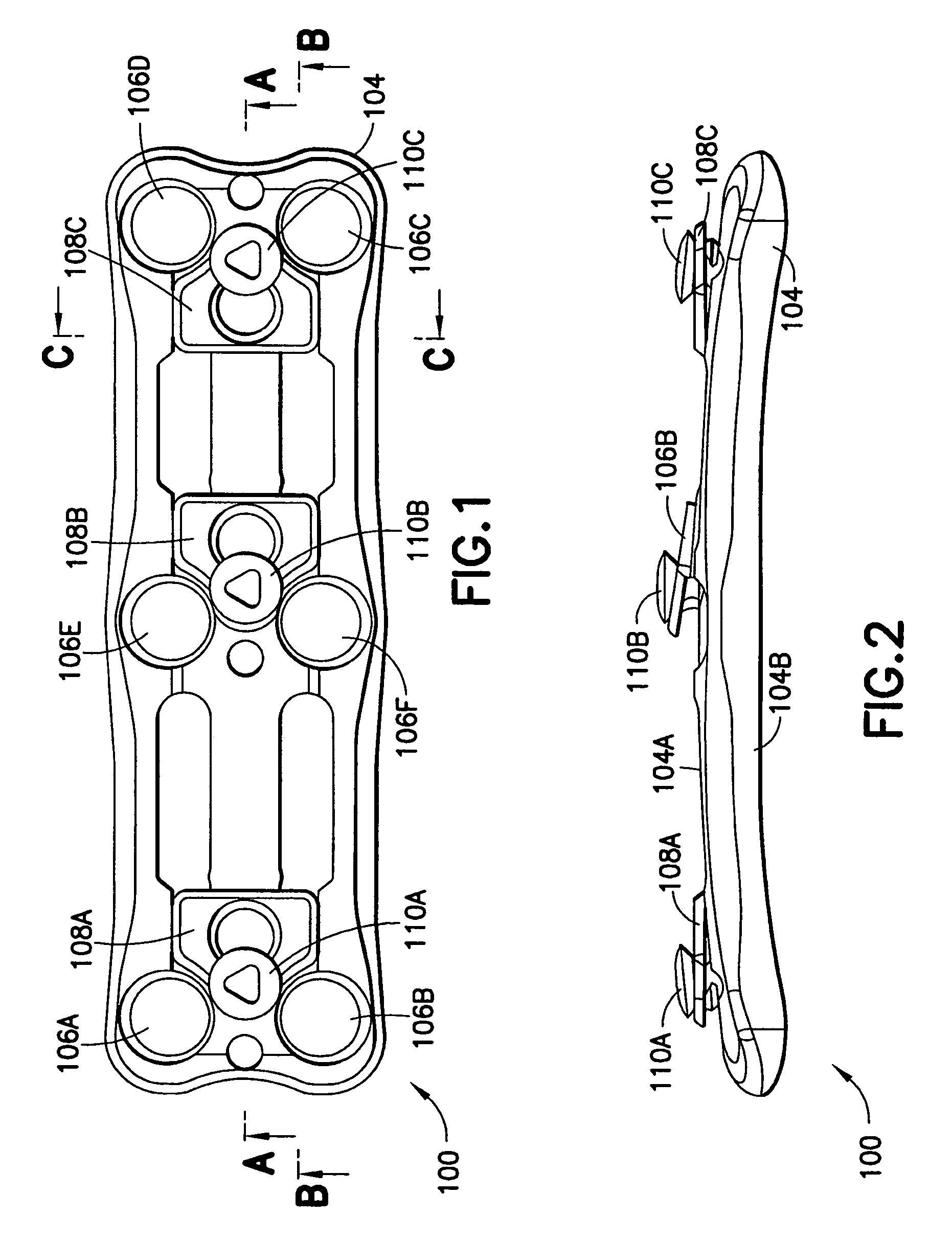
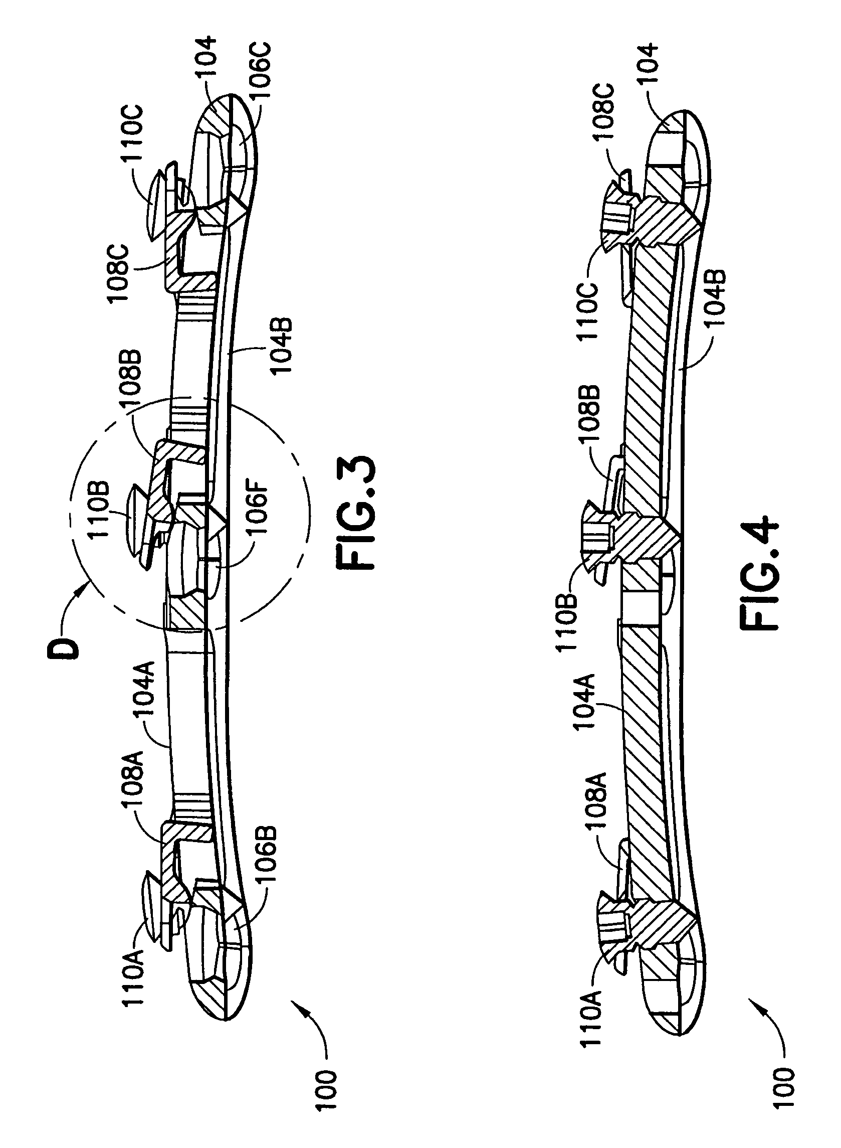
[0016]Referring now to FIGS. 1-14, a first embodiment of the present invention is shown. As seen in these FIGS., implant assembly 100 may be adapted to be fix...


PUM


Abstract

Disclosed are systems and methods for spinal fusion and particularly, anterior cervical plating systems with a toggle pivotally mounted to a bone plate with at least two degrees of freedom of movement. In a particular embodiment, each toggle plate is slidably attached and pivotally mounted to the bone plate by a locking screw having an axis such that in at least one slidable position each toggle plate can pivot relative to the axis of the locking screw in the bone plate.

Description

FIELD OF THE INVENTION[0001]The present invention relates to systems and methods for spinal fusion.[0002]More particularly, one embodiment of the present invention relates to an anterior cervical plating system.[0003]For the purposes of describing and claiming the present invention, the term “plate” is intended to refer to any three-dimensional structure (i.e., not necessarily a flat structure). In this regard, such plate may be curved along one or more axis and may have one or more apertures or other features therein and / or thereon.[0004]Further, for the purposes of describing and claiming the present invention, the term “aperture” is intended to refer to any hole or space (i.e., not necessarily round). In this regard, such an aperture may be round, oval, square, rectangular (or any other desired shape) and may be totally surrounded by material (e.g., a “hole” through an item) or may be partially surrounded by material (e.g., a “slot” or “indentation” at a perimeter of an item).BAC...

Claims


Application Information

Patent Timeline
Patent Type & Authority Patents(United States)
IPC IPC(8): A61B17/80
CPCA61B17/1604A61B17/1728A61B17/7059A61B17/8042A61B17/8875A61B17/92A61B17/8863A61B17/1633A61B17/1655A61B2090/036A61B2017/00464A61B17/1757A61B2090/031
Inventor RIBEIRO, HELIO MARCOS
Owner ORTHOFIX US LLC
Why Eureka
Try Eureka