Eureka AIR delivers breakthrough ideas for toughest innovation challenges, trusted by R&D personnel around the world.

Handle assembly

a technology of swing handle and assembly, which is applied in the direction of wing knob, carpet fastener, dwelling equipment, etc., can solve the problems of high-security locking means that cannot be satisfactorily accommodated, locking means that can be a target for vandals to destroy, and lock means that can be easily tampered with

Inactive Publication Date: 2010-02-23
DAVID STUCKEY INVESTMENTS
View PDF11 Cites 17 Cited by
  • Summary
  • Abstract
  • Description
  • Claims
  • Application Information

AI Technical Summary

Benefits of technology

[0005]According to one aspect of the present invention, there is provided a swing handle assembly comprising a lockable handle member which when pivotally swung into cooperable alignment with a frame enables the assembly to be placed in a locked condition, wherein the end of the handle member distal from the pivotally attached end comprises a substantially deformable housing located therebeneath, the housing being adapted to at least partially support a locking means when located therein, whereby when the assembly is locked and the locking means is subjected to a destructive outside force sufficient to cause deformation of the housing, the locked condition of the assembly is substantially maintained.
[0012]The housing is preferably a substantially obround member having a box-like body comprising a lower wall having substantially upwardly side walls and opposed end walls extending therefrom, which end walls are of a substantially semi-circular configuration, wherein the lower wall or one or both of the side wall(s) is / are provided with cut-out region(s) which act to expose the lock actuator to enable the lock actuator to move between a locked and an unlocked position. More preferably, one of the opposed end walls is chamfered relative to the other opposed end wall to facilitate receipt or removal of the housing relative to the second opening of the frame.
[0014]The provision of the housing therefore not only offers support for and correct alignment of the locking means relative to the opening in the base section of the frame, but it also provides added protection to the handle assembly. Should an intruder attempt to break open the handle assembly by trying to smash the assembly, the housing acts to substantially prevent the locking means from being able to be placed in an unlocked position and as such it can hold the locking means in place relative to the handle member. Should however the intruder succeed in fracturing the housing, the resulting debris from the broken or shattered housing made up of the lower wall, opposed end walls and / or side walls can fill the available space surrounding the lock actuator, such that the actuator is unable to rotate and thus remains in locked contact with the frame.
[0015]In a further aspect of the invention, there is also provided a spacer means for use with any handle assembly and preferably, the handle assembly of the invention being substantially attachable to or integral with a handle member, the spacer means being able to substantially engage with or sit on the handle member, wherein the spacer means acts to hold the handle member above or out of contact with an area surrounding the assembly. Preferably, the spacer means is of a substantially T-shaped configuration having a stem and cross-piece, wherein the stem piece is able to be substantially retained within the handle member, while the cross-piece is able to substantially engage with or sit on the underside region of the handle member. In this way, scratching of and damage of this area can be significantly reduced.

Problems solved by technology

However, a problem associated with prior assemblies is that the locking means contained therein can easily be tampered with by vandals trying to smash and destroy the locking means to render it inoperable and thus then gain easy access to the otherwise secure enclosure.
However, it has subsequently been found that such high security locking means could not be satisfactorily accommodated and yet still function as required within existing handles.
It was discovered that sometimes the high security locking means inadvertently protruded from the upper surface of the handle, thereby exposing the locking means as a target for vandals to destroy.

Method used


Image

  • Handle assembly
  • Handle assembly
  • Handle assembly

Examples


Embodiment Construction

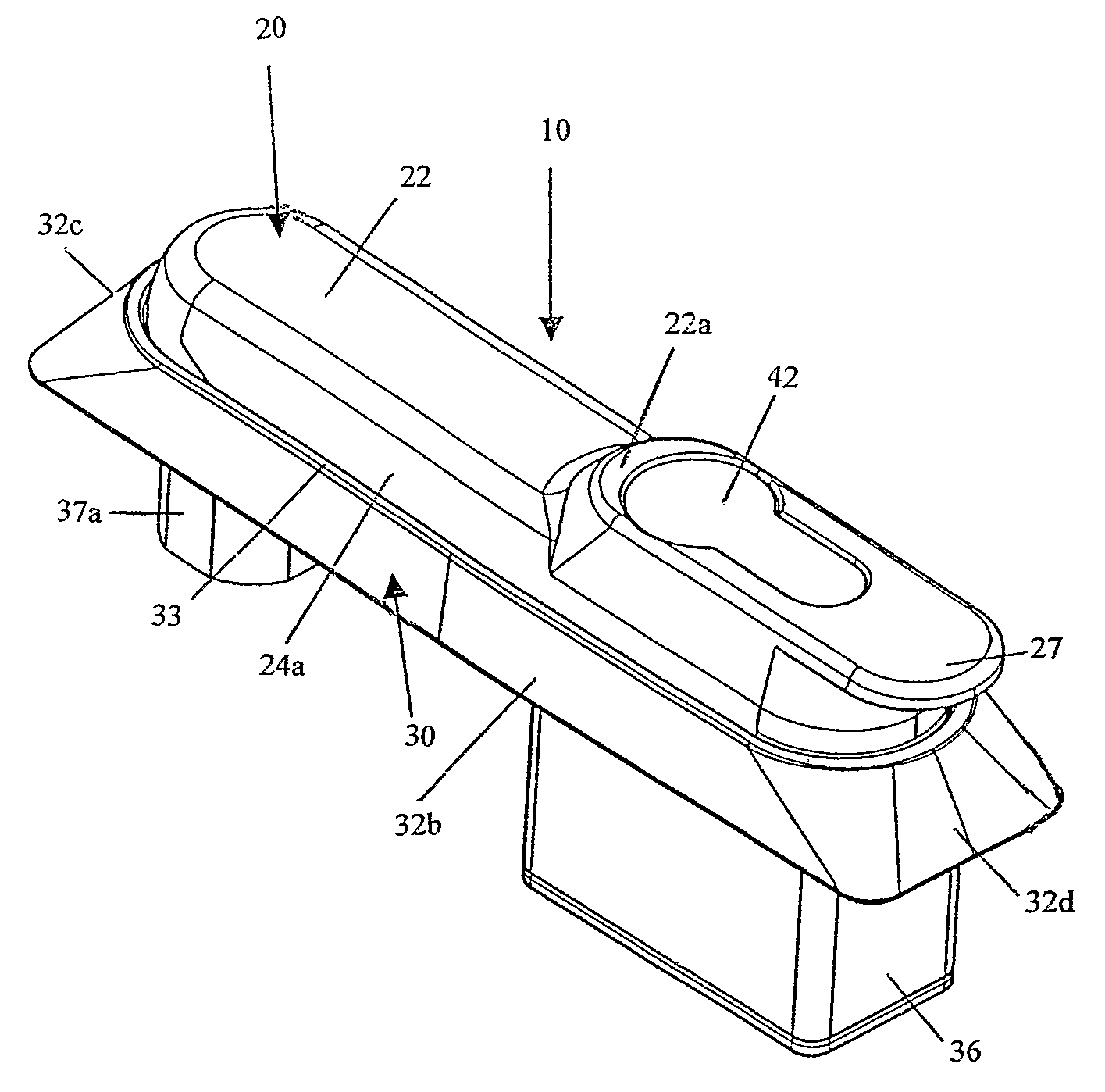
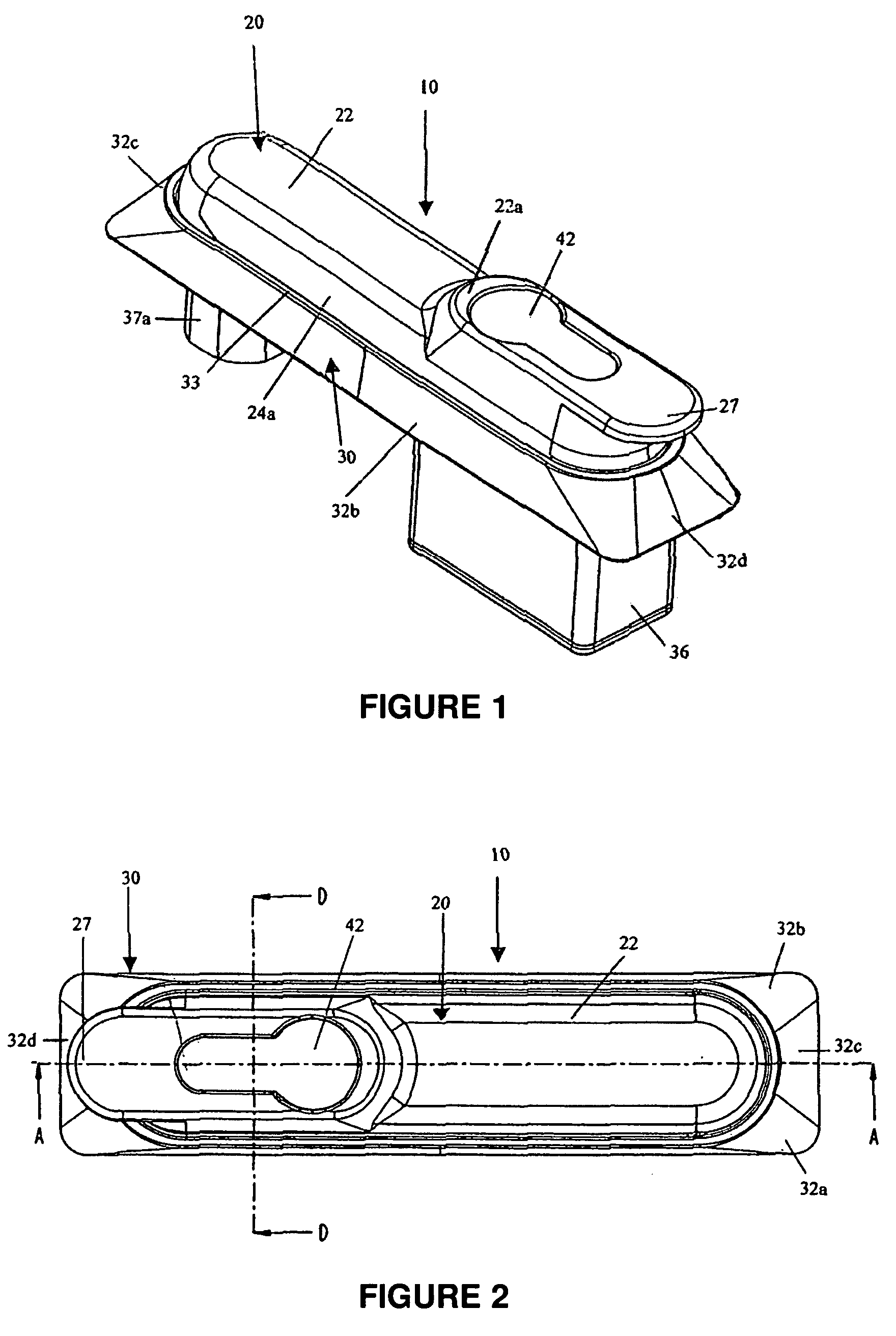
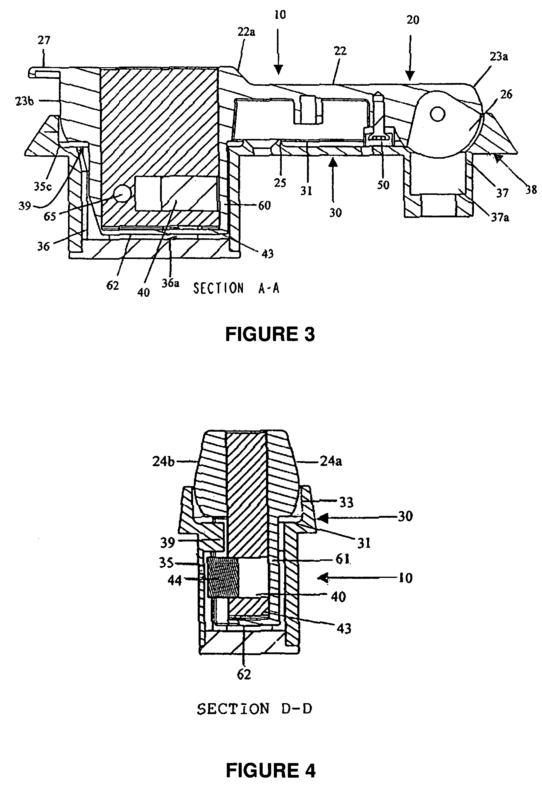
[0027]Referring to all the drawings wherein like reference numerals designate like or corresponding parts throughout the several views, an assembled view of an embodiment of the handle assembly 10 is shown. The handle assembly 10 generally comprises a handle member 20, preferably in the general shape of an obround and a frame 30 of preferably a substantially rectangular configuration. In order to place the handle member 20 into locked engagement with the frame 30, there is preferably provided a locking means 40, preferably in the form of a barrel / cylinder lock means, supported by a housing 60, which is securable to or integral with the handle member 20. The combination of the handle member 20, the locking means 40 and the frame 30, to which the handle member 20 is locked, form a locking device that may be placed in a locked or unlocked condition. Where the handle member 20 is fitted to or upon a lock-actuating shaft 37a, the user thereof is able to place the locking shaft 37a and an...


PUM


Abstract

A swing handle assembly (10) comprising a lockable handle member (20) which when pivotally swung into co-operable alignment with a frame (30) enables the assembly (10) to be placed in a locked condition, wherein the end of the handle member distal from the pivotally attached end comprises a substantially deformable housing (60) located therebeneath, the housing (60) being adapted to support a lock actuator (44), whereby when the assembly is locked and when a destructive outside force sufficient to cause deformation of the housing (60) the locked condition of the assembly (10) is substantially maintained.

Description

FIELD OF THE INVENTION[0001]The invention generally relates to a swing handle assembly which is particularly useful as handle hardware on metal enclosures. The metal enclosures may include doors to storage areas and boxes, electrical switch-gear cabinets or other high security applications. In particular, the invention relates to a swing handle assembly for use in high security locking applications. It will be convenient to hereinafter describe the invention in relation to these particular applications. It should be appreciated however that the present invention is not limited to these applications only.BACKGROUND TO THE INVENTION[0002]Barriers or doors for entry and exit from metal enclosures, which are used as storage areas, necessarily require a handle with an internal latch or locking mechanism for security and safety. These handle and locking mechanisms, being most conveniently operable by means of a key, primarily function to provide a means of preventing unauthorised personne...

Claims


Application Information

Patent Timeline
Patent Type & Authority Patents(United States)
IPC IPC(8): E05B13/10
CPCE05B1/0092E05B13/10E05B17/0062F25D23/028Y10S292/31Y10T70/5761Y10T70/577Y10T70/5792Y10T70/7949Y10T292/57Y10T292/82E05B1/00E05B7/00E05B17/00
Inventor STUCKEY, DAVID MARTIN
Owner DAVID STUCKEY INVESTMENTS
Why Eureka
Eureka Blog
Learn More