Method and system for determining antenna characterization

a technology for antennas and antenna arrays, applied in the field of antennas, can solve the problems of limiting the number of facilities, wasting time and money, and wasting time, and avoiding further such time-consuming and expensive testing

Inactive Publication Date: 2010-02-23
BAE SYST INFORMATION & ELECTRONICS SYST INTERGRATION INC
View PDF9 Cites 5 Cited by
  • Summary
  • Abstract
  • Description
  • Claims
  • Application Information

AI Technical Summary

Benefits of technology

[0014]A further aspect of the invention is to initially field test a first antenna (gold standard antenna) in a radar cross-section range test facility, an antenna range test facility and vector analysis testing, which once completed for the “gold antenna” standard, avoids further such time consuming and expensive testing for all subsequent substantially similar antennas in order to determine the antenna characterization thereof.

Problems solved by technology

A conventional full characterization of antenna parameters is an expensive and time-consuming process involving tests in multiple measurement facilities especially for measuring arrays of antennas.
Measuring a large number of antennas as in an antenna array, at three separate facilities is an expensive and time-consuming procedure.
The facilities themselves are rare and expensive enough to be limiting by schedule competition with other programs.
To measure and determine the antenna characterization or S-parameters of many types of antennas, and in particular arrays of antenna, requires considerable time expenditure depending upon the particular antenna or antenna array.
For example, a one month estimate and considerable costs for characterizing a 6-element (6 antenna) array.
This becomes a problem when a vast number of similar antennas are produced, which are substantially similar to each other, especially antenna arrays.
It is required that each antenna be tested before shipment for commercial use which increases considerably the cost of the antenna and the delivery schedule.
It also requires constant access to conventional test facilities and chambers which are expensive to construct, operate or lease, and presents timing problems, especially when shared with the testing of other antennas.

Method used


Image

  • Method and system for determining antenna characterization
  • Method and system for determining antenna characterization
  • Method and system for determining antenna characterization

Examples


Embodiment Construction

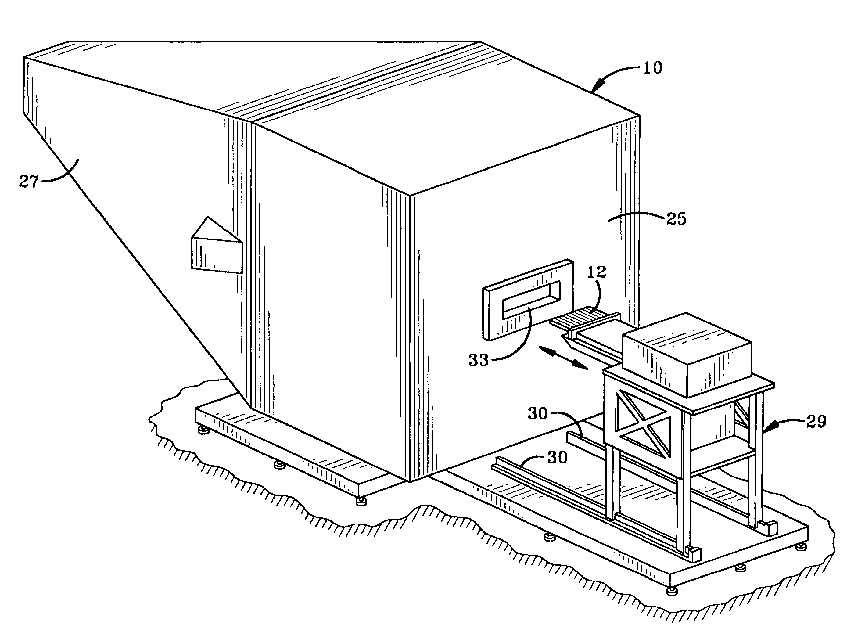
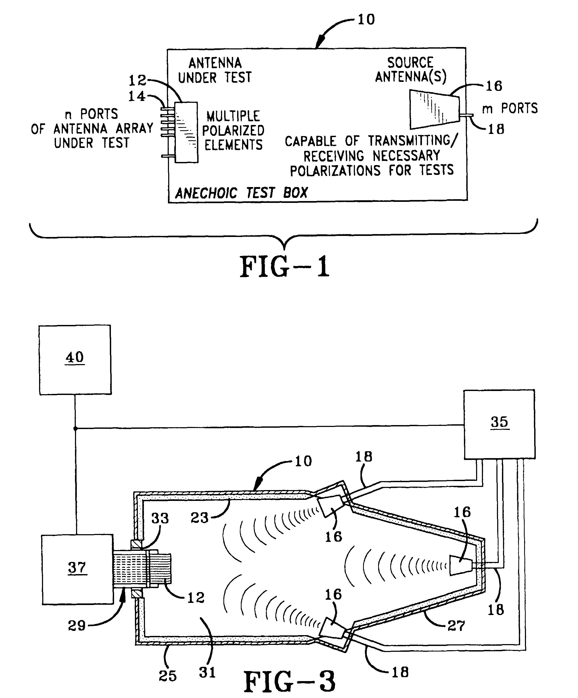
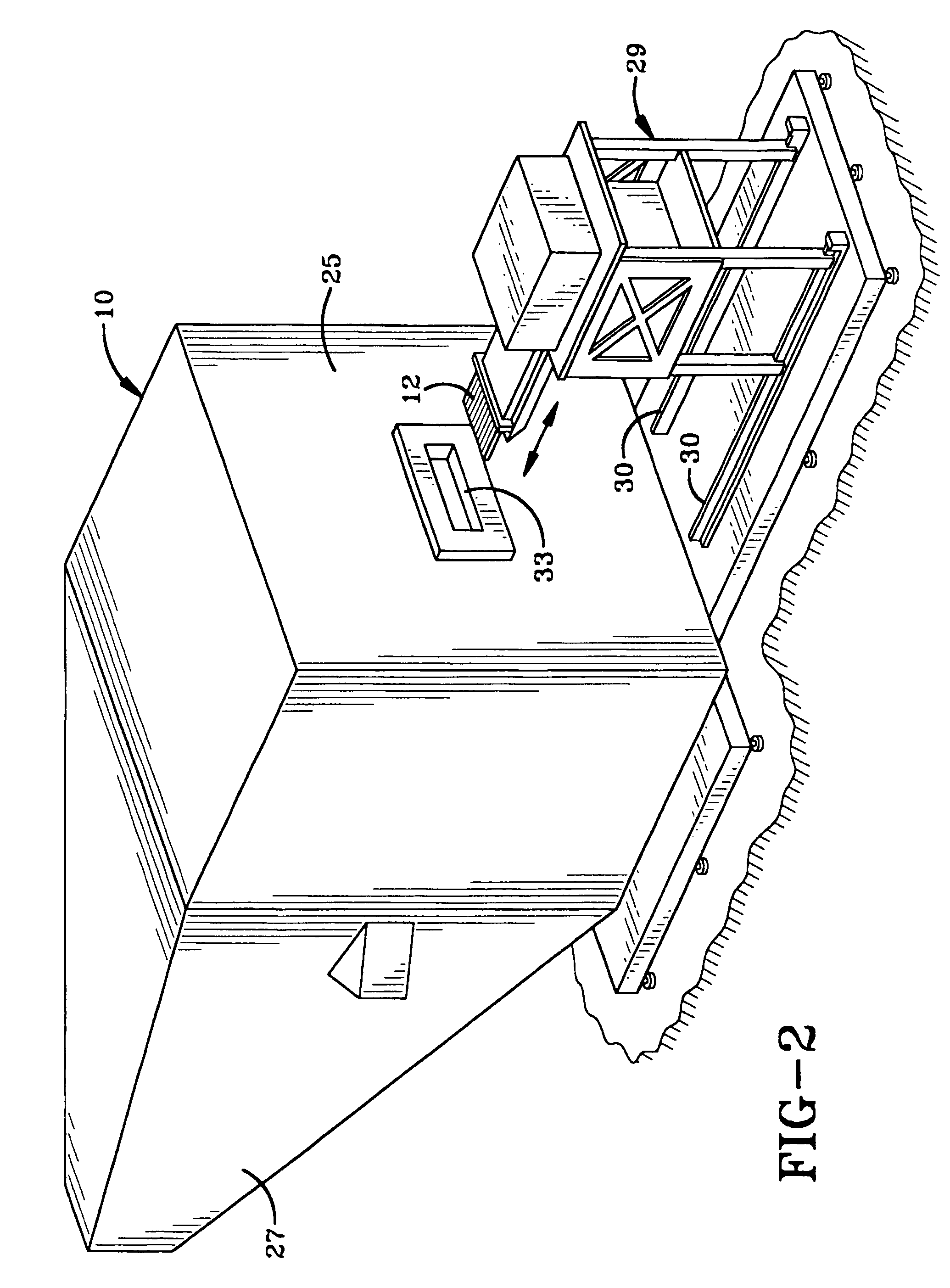
[0021]Referring to FIG. 1, an anechoic test box 10 is shown on which there is mounted the Antenna Under Test (AUT) 12 with multiple polarized elements and N ports as at 14. There is also a source antenna 16 with M ports as at 18. AUT 12 can be a single antenna, an antenna array, etc. without affecting the concept of the invention.

[0022]A given test may include inputs / outputs from the antenna under test (AUT), the source antenna (or any type of measurement antenna), or both the AUT and Source antenna. The AUT is located on a fixture with discrete rotational capabilities for use in data collection at various precalculated or empirically determined angels. The resulting S-parameters of the “gold” AUT and fixture, treated as a “black box”, are then compared to the resultant S-parameters of the same fixture with subsequent AUT's. Similar electrical performances (within allowed tolerances) of each “black box” configuration indicate similar antenna characteristics.

[0023]By characterizing o...


PUM


Abstract

An antenna and its associated components are consolidated in a small measurement box, and multiple tests are competed simultaneously, with a single vector network analyzer. This can be done by treating the “Far Field” measurements (typically measured on antenna / RCS ranges) as another port of a larger passive network. After characterization of one ideal “gold” unit (or a sample set of “gold” units), the S-parameters of subsequent units are measured in the same passive test box environment. The results of these subsequent tests are compared to the results of the “gold unit's” test, and if they are repeated to within some tolerance, electrical similarity can be proven.

Description

CROSS REFERENCE TO RELATED APPLICATION[0001]This application claims rights under 35 USC 119(e) from U.S. application Ser. No. 60 / 599,738, filed Aug. 6, 2004, the contents of which are incorporated herein by reference.STATEMENT OF GOVERNMENT INTEREST[0002]The invention was made with Government support under Contract (Grant) No. M4422 awarded by the Air Force. The Government has certain rights in this invention.BACKGROUND OF THE INVENTION[0003]1. Technical Field[0004]The present invention relates to antennas and more particularly to a system and process for the characterization of antennas. More particularly the invention relates to a method, system and related apparatus for determining the S-parameters of a plurality of similar antennas, such as in an antenna array, in a rapid and repeatable fashion in an effective, yet inexpensive procedure and at a single test facility.[0005]2. Background Information[0006]A conventional full characterization of antenna parameters is an expensive an...

Claims


Application Information

Patent Timeline
Patent Type & Authority Patents(United States)
IPC IPC(8): G01R27/04G01R35/00H01L35/00
CPCG01R27/28G01R29/105G01S7/4086
Inventor KHOSRAVI, MAHMOOD F.LOMBARDI, ROBERT B.SPENCER, DONALD B.RUVINSKY, LEONARDFREEMAN, MICHAEL C.
Owner BAE SYST INFORMATION & ELECTRONICS SYST INTERGRATION INC
Why Eureka
Try Eureka