Interface apparatus for passive tracking systems and method of use thereof

a technology of passive tracking and interface apparatus, which is applied in the direction of speed/acceleration/shock measurement device testing/calibration, sensors, diagnostics, etc., can solve the problems of inability to use mouse in the sterile zone to perform such actions, difficult to achieve the effect of achieving the effect of achieving sterility, and inconvenient us

Active Publication Date: 2010-02-23
ORTHOSOFT
View PDF3 Cites 29 Cited by
  • Summary
  • Abstract
  • Description
  • Claims
  • Application Information

AI Technical Summary

Problems solved by technology

The interaction between the surgeon and the CAS system presents some difficulties.
However, due to the need for all objects in the sterile zone of the operating room to be sterile, a mouse cannot be used in the sterile zone to perform such actions.
This technique is both tedious and inefficient.

Method used


Image

  • Interface apparatus for passive tracking systems and method of use thereof
  • Interface apparatus for passive tracking systems and method of use thereof
  • Interface apparatus for passive tracking systems and method of use thereof

Examples


first embodiment

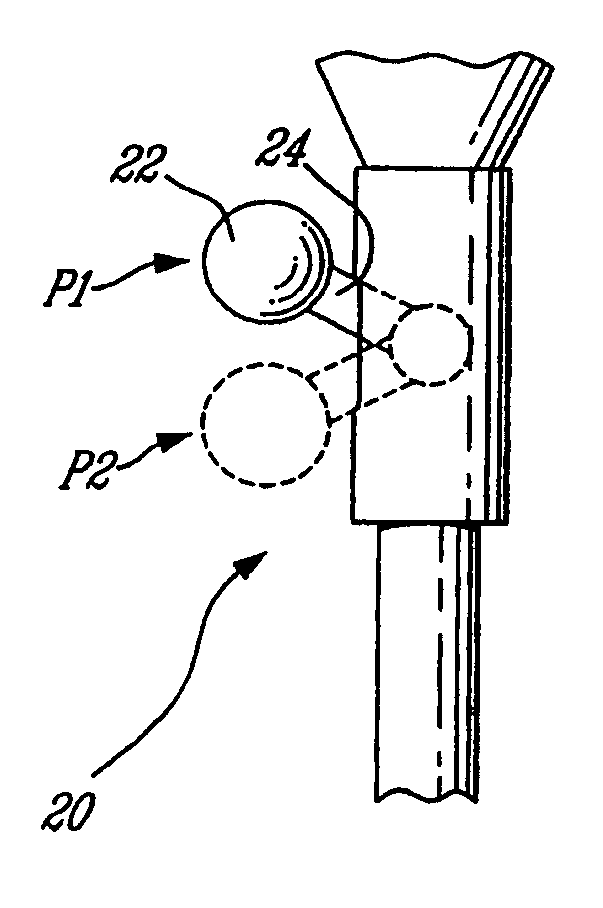
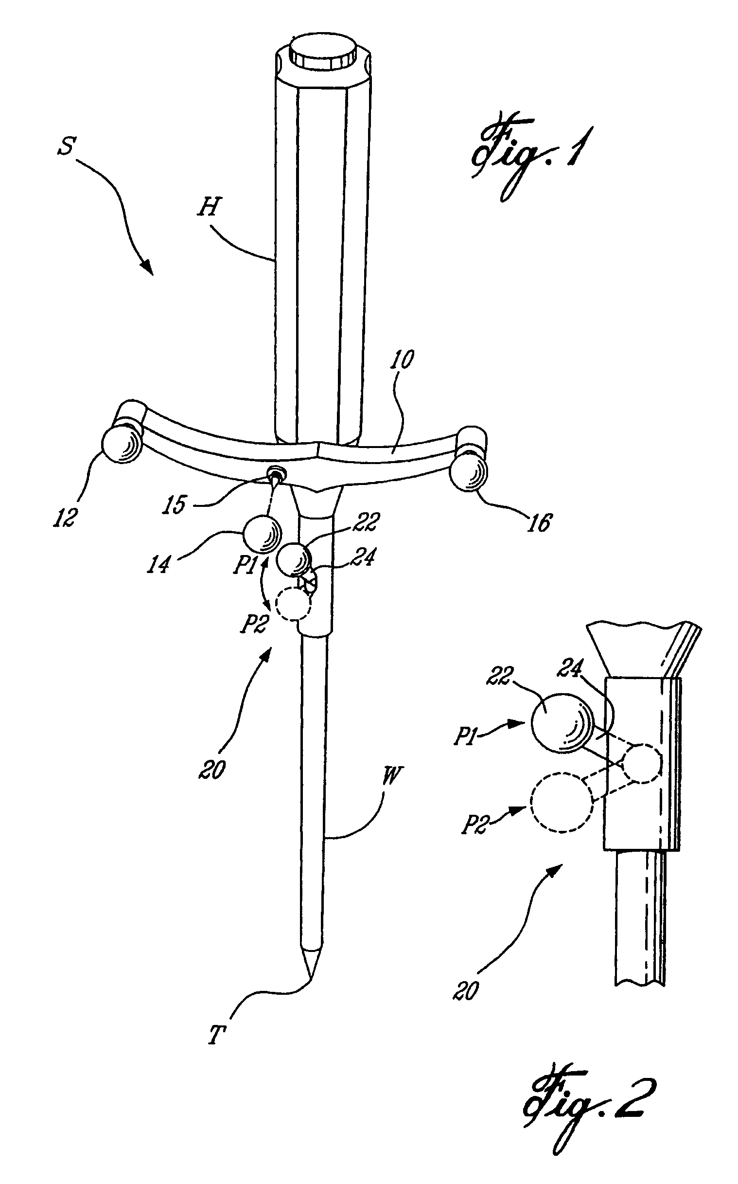
[0021]In the present invention, the detectable sphere 22 is used with two of the three spheres on the blade 10 in order to make another optically detectable geometrical pattern. For instance, detectable spheres 12, 14 and 22 form a geometrical pattern (hereinafter referred to as pattern 12-14-P1) when the detectable 12-14-P1 is tracked for position and orientation simultaneously with the tracking of the geometrical pattern 12-14-16. As the tool S and all detectable spheres thereon are tracked for position and orientation, a move of the detectable sphere 22 from position P1 to position P2 will modify the optical pattern 12-14-P1, and this will be detected by the interactive tracking system 18. The modification detected by the interactive tracking system 18 will be interpreted as an interaction signal thereby. Accordingly, the tool operator is enabled to send a signal to the interactive tracking system 18 by flicking the lever 24 out of position P1, and this is equivalent to a “click”...

second embodiment

[0022]In the present invention, a vector is defined between the detectable sphere 22 at one position and one of the detectable spheres 12, 14 and 16. For instance, having detectable sphere 12 as the reference point, a vector is defined between the detectable sphere 22 at position P1 and the detectable sphere 12, and is referred to as vector 12-P1. A modification of the vector 12-P1 by a displacement of the detectable sphere 22 is detected by the interactive tracking system 18 of the CAS system, which will then send a signal to the CAS system. It is pointed out that a vector 12-P2 (i.e., with the detectable sphere at position P2) may be used as a second position and orientation, similar to the ON / OFF switching described above.

[0023]The interactive tracking system 18 is typically an optical tracking system capable of tracking the real-time position and orientation of at least three detectable devices in a working space. However, although the preferred embodiments of the present invent...


PUM


Abstract

An interface apparatus (20) for tracking by a tracking system (40) of an object(s) in space for position and orientation and for interacting with the tracking system (40). The interface apparatus (30) comprises passive detectable devices (12,14,16,22) trackable for position by the tracking system (40). A mounting device (10,24) receives the passive detectable devices (12,14,16,22) in a known geometry, and is secured to the object(s) such that a position and orientation of the object(s) is calculable by the tracking system (40) as a function of a tracking of the known geometry of the passive detectable devices (12,14,16,22). One of the passive detectable devices (22) is displaceable with respect to the object(s). A displacement of the passive detectable device (22) with respect to the object(s) is detectable to initiate an interaction with the tracking system (40) while maintaining the tracking of the object(s).

Description

CROSS-REFERENCE TO RELATED APPLICATION [0001]This application is a national entry of International Patent Application No. PCT / CA2003 / 001217, filed on Aug. 11, 2003, and claims priority on U.S. Provisional Patent Application No. 60 / 403,642, filed on Aug. 16, 2002.FIELD OF THE INVENTION [0002]The present invention generally relates to optical tracking systems and, more particularly but not exclusively, to interaction between a tool operator and a tracking system.BACKGROUND OF THE INVENTION [0003]There are many advantages to being able to operate a computer-aided surgery (CAS) system in an operating room. For a system that allows real-time display of the relative positions of three-dimensional models of anatomical structures and of a surgical tool by tracking of the latter, this means being able to select a component or section of an image displayed on a monitor and perform operations on it such as zooming in and out, rotating it, etc. It also means enabling a surgeon to digitize point...

Claims


Application Information

Patent Timeline
Patent Type & Authority Patents(United States)
IPC IPC(8): A61B5/05A61B19/00
CPCA61B19/5244A61B19/54A61B2017/00207A61B2019/2269A61B2019/5255A61B2019/5268A61B2019/5483A61B2090/3983A61B2034/2055A61B2034/2068A61B34/20A61B34/74A61B90/39
Inventor JANSEN, HERBERT ANDRE
Owner ORTHOSOFT
Why Eureka
Try Eureka