Methods of networking interrogation devices for structural conditions

a network interrogation device and structural condition technology, applied in the field of structural condition diagnosis, can solve the problems of time-consuming and expensive passive diagnostic system, difficulty in regional monitoring and adaptive self-sensing, and increased complexity of arranging and operating patches

Inactive Publication Date: 2010-02-23
ADVANCED STRUCTURE MONITORING
View PDF57 Cites 55 Cited by
  • Summary
  • Abstract
  • Description
  • Claims
  • Application Information

AI Technical Summary

Problems solved by technology

Although still used for inspection of isolated locations, they are time-consuming and expensive.
Such passive diagnostic systems have difficulties in regional monitoring and adaptive self sensing.
As the number of patches in the active systems has increased, the complexity in arranging and operating the patches also has increased.

Method used


Image

  • Methods of networking interrogation devices for structural conditions
  • Methods of networking interrogation devices for structural conditions
  • Methods of networking interrogation devices for structural conditions

Examples


Embodiment Construction

[0031]Although the following detained description contains many specifics for the purposes of illustration, those of ordinary skill in the art will appreciate that many variations and alterations to the following detains are within the scope of the invention. Accordingly, the following embodiments of the invention are set forth without any loss of generality to, and without imposing limitation upon, the claimed invention.

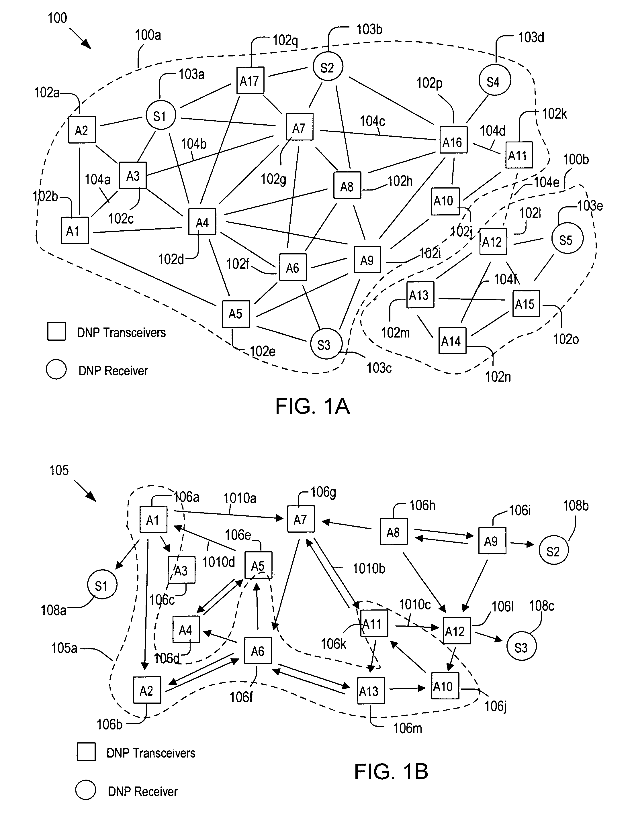
[0032]FIG. 1A shows an undirected Euclidean graph 100 for networking patches 102 and 103 in accordance with one embodiment. The patches 102 may be transceivers that can generate and / or respond to Lamb waves while the patches 103 may be receivers that can only develop electrical signals in response to the Lamb waves. More detailed description of the patches or nodes 102 and 103 can be found in the previously referenced U.S. patent applications, Ser. No. 10 / 942,714, filed on Sep. 16, 2004 and issued as U.S. Pat. No. 7,286,964, Ser. No 10 / 942,366, filed on Sep. 16, 200...


PUM

PropertyMeasurementUnit
energyaaaaaaaaaa
temperatureaaaaaaaaaa
pressureaaaaaaaaaa

Abstract

Methods of operating an interrogation system that has a plurality of patches attached to a host structure. Each patch is capable of generating a diagnostic wave and / or developing a sensor signal in response to the diagnostic wave. In each method, a Euclidean undirected graph is generated by forming a plurality of paths; wherein each path connects two of the patches and the length of the path is shorter than a preset limit. Then, a directed graph or network is generated by assigning a propagation direction of the diagnostic wave to each path. Structural condition index (SCI) values are measured by use of the directed graph and, based on the SCI values, the host structure is scanned for anomalies. The directed graph is reconfigured to determine the shape and location of the anomalies.

Description

CROSS REFERENCE TO RELATED APPLICATIONS[0001]This application is a continuation-in-part of application Ser. No. 10 / 942,714, filed on Sep. 16, 2004 and issued as U.S. Pat. No. 7,286,964, which claims the benefit of U.S. Provisional Application No. 60 / 505,120, filed on Sep. 22, 2003.BACKGROUND[0002]The present invention relates to diagnostics of structures, and more particularly to diagnostic network patch (DNP) systems for monitoring structural conditions.[0003]In general, structures in service may require periodic inspections and appropriate maintenance services to prolong their life and / or to prevent catastrophic failures. Numerous methods have been employed to identify fault or damage of structures, where these methods may include conventional visual inspection and non-destructive techniques, such as ultrasonic and eddy current scanning, acoustic emission and X-ray inspection. These conventional methods require at least temporary removal of structures from service for inspection. ...

Claims


Application Information

Patent Timeline
Patent Type & Authority Patents(United States)
IPC IPC(8): G01H17/00G06F17/00G01N29/06G01N29/07G01N29/22G01N29/28G01N29/44G21C17/00
CPCG01H9/004G01H11/00G01H11/08G01M5/0033G01M5/0066G01M5/0091G01N29/043G01N29/0609G01N29/0672G01N29/07G01N29/223G01N29/245G01N29/2475G01N29/2493G01N29/28G01N29/4418G01N29/4463G01N2291/011G01N2291/015G01N2291/02491G01N2291/0258G01N2291/0422G01N2291/0423G01N2291/0427G01N2291/106
Inventor KIM, HYEUNG-YUN
Owner ADVANCED STRUCTURE MONITORING
Why Eureka
Try Eureka