Tool retaining or connecting device

a technology of tool retaining or connecting device, which is applied in the direction of chucks, mechanical equipment, manufacturing tools, etc., can solve the problems of increasing manufacturing costs

Inactive Publication Date: 2010-03-02
HSIN YING ENTERPRISE
View PDF18 Cites 52 Cited by
  • Summary
  • Abstract
  • Description
  • Claims
  • Application Information

AI Technical Summary

Problems solved by technology

However, the typical locking quick-change chuck assemblies comprise a rather complicated configuration that may not be easily manufactured and assembled and that may include a greatly increased manufacturing cost.

Method used


Image

  • Tool retaining or connecting device
  • Tool retaining or connecting device
  • Tool retaining or connecting device

Examples


Embodiment Construction

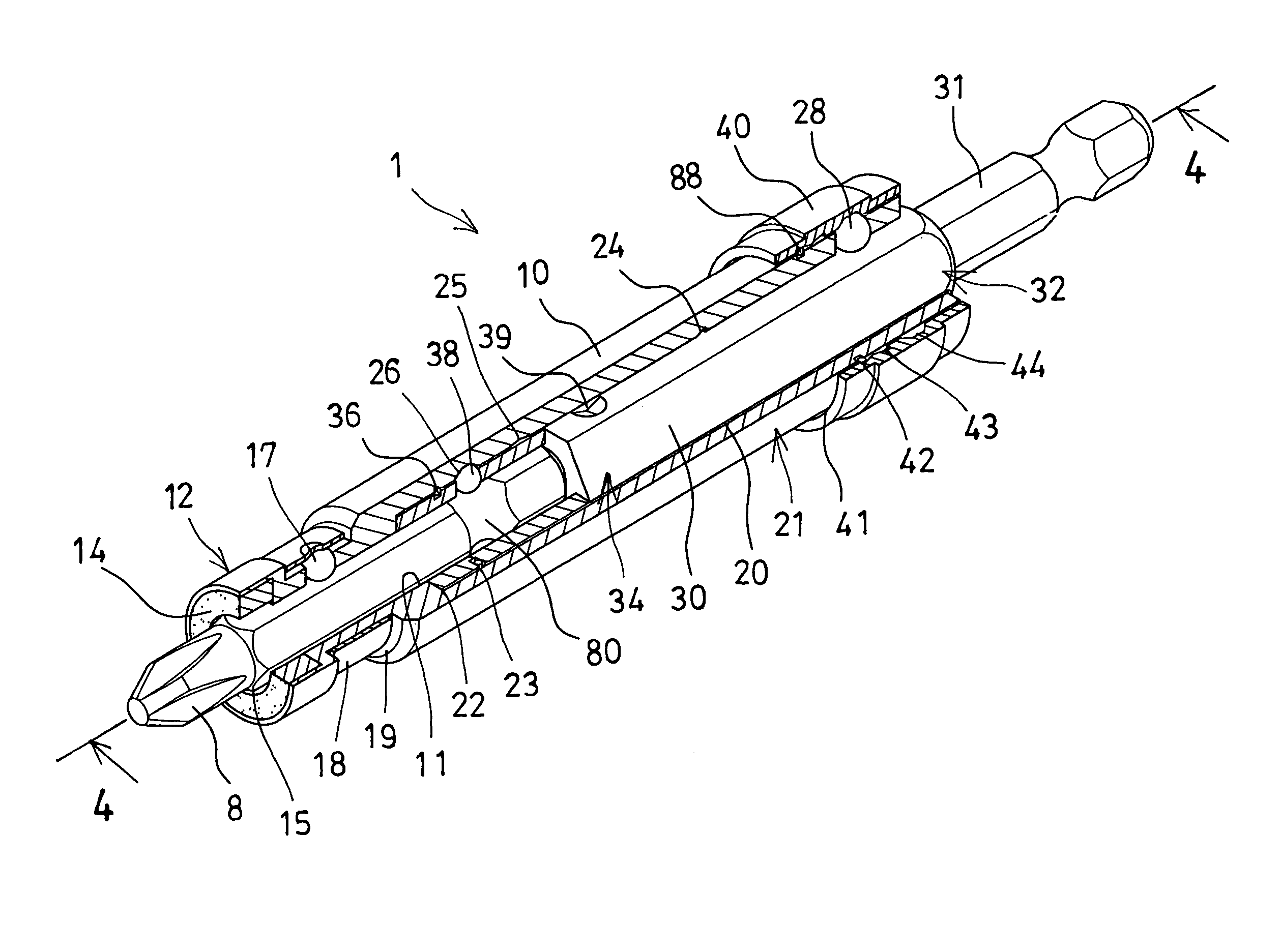
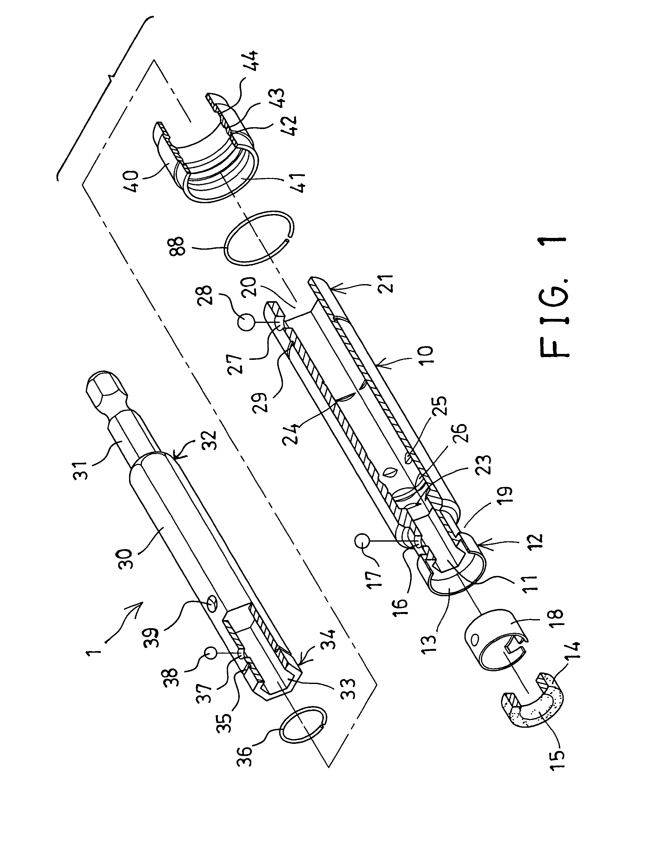
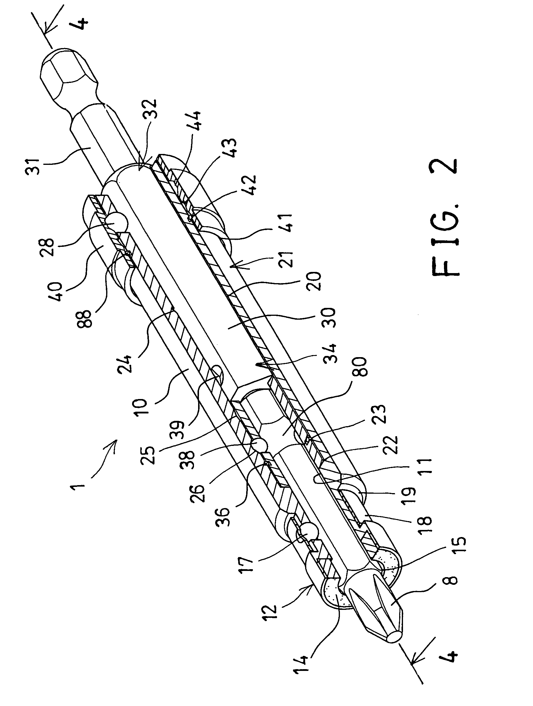
[0029]Referring to the drawings, and initially to FIGS. 1-4, a tool retaining or connecting device 1 in accordance with the present invention comprises an outer housing 10 including an engaging hole 11 formed in one end 12 thereof and preferably having a non-circular cross section, such as a hexagonal cross section for receiving and for engaging with a tool member 8, such as a tool bit 8 and for allowing the tool member or tool bit 8 to be rotated or driven by the housing 10. The housing 10 further includes an enlarged compartment 13 formed in the one end 12 thereof and communicating with the engaging hole 11 of the housing 10 for receiving a ring or annular shaped magnetic member 14 which includes a bore 15 formed therein for slidably receiving the tool member or tool bit 8 (FIGS. 2 and 4-5).

[0030]The housing 10 further includes an orifice 16 formed in the one end 12 thereof and intersecting or communicating with the engaging hole 11 of the housing 10 for receiving a bit detent bal...


PUM


Abstract

A tool retaining device includes a housing having an engaging hole and having a chamber for slidably receiving a tool stem, the tool stem includes a socket opening for receiving a tool member which is also slidably engaged in the engaging hole of the housing, for allowing the tool member to be rotated by either the tool stem or the housing. The tool member may also be moved relative to the housing for changeably coupling tool members or tool bits having different lengths, and may be selectively moved into the housing, for allowing another tool element to be selectively engaged with the engaging hole of the housing when the tool member is moved into the housing.

Description

BACKGROUND OF THE INVENTION[0001]1. Field of the Invention[0002]The present invention relates to a tool retaining or connecting device, and more particularly to a tool retaining device changeably coupling or retaining different tool members or tool bits having different lengths.[0003]2. Description of the Prior Art[0004]Typical tool devices or tool shanks or tool extensions may comprise an engaging hole formed in one end for receiving a tool member or tool bit, and a retaining or connecting device or quick-change chuck device attached onto the one end thereof for engaging with and for retaining or connecting the tool member or tool bit to the tool devices or tool shanks or tool extensions.[0005]For example, U.S. Pat. No. 6,457,916 to Wienhold discloses one of the typical locking quick-change chuck assemblies comprising a chuck hub having a longitudinally extending bore therein for receiving a tool member or tool bit, and a shuttle slidably disposed in the longitudinally extending bo...

Claims


Application Information

Patent Timeline
Patent Type & Authority Patents(United States)
IPC IPC(8): B23B31/06B23B31/107
CPCB23B31/008B23B31/1071B23B51/12B25B15/001B25B21/007B25B23/12B23B2231/48Y10T279/23Y10T279/17008Y10T279/3406Y10T279/29Y10T279/17811Y10T279/17461
Inventor CHIANG, WEN HUNG
Owner HSIN YING ENTERPRISE
Why Eureka
Try Eureka