
Medical device with articulating shaft

a technology of articulating shafts and medical devices, which is applied in the field of surgical devices and methods, can solve the problems of increasing the complexity of surgical procedures, complex mechanisms that are expensive to manufacture and difficult to assemble, and bending the shaft in only one direction

Active Publication Date: 2010-03-02
BANNERMAN BRETT
View PDF137 Cites 64 Cited by
  • Summary
  • Abstract
  • Description
  • Claims
  • Application Information

AI Technical Summary

Benefits of technology

"The present invention provides a medical device with a bendable portion that can be controlled to bend in different directions. The bendable portion is made up of a plurality of pivot members and pins that are arranged in an alternating configuration. The device also includes first and second slat assemblies that are connected to the bendable portion and can be pushed and pulled to cause the bendable portion to bend. The bendable portion can be used in various medical applications such as catheters and endoscopes. The technical effects of the invention include improved control and flexibility when bending the device, as well as a more efficient and compact design."

Problems solved by technology

Articulating shafts in the prior art include complex mechanisms that are expensive to manufacture and difficult to assemble.
These complexities have derived, at least in part, from the need to provide tension in order to cause the shaft to bend.
Since the pathway to a particular desired location in a human body is often circuitous in more intricate surgical procedures, bending a shaft in only one direction can be very limiting.
Of course, having to manipulate a knob to rotate a shaft and then having to pull a tension mechanism to bend a shaft increases the complexity of a surgical procedure.
Articulating shafts in the prior art are also highly complex.
These complexities have derived from the requirement of bending a distal portion of a shaft with a mechanism located at a proximal end of a medical device.
Such complexities relate to both the manufacturing and operation of these devices.
Prior art articulating shafts also lack rigidity.
This is due at least in part to the fact that tensioning mechanisms in the prior art do not provide sufficient rigidity.
Under standard use, prior art shafts are often unable to maintain a sufficient articulated form or shape.
No simple structure has been devised to accomplish ease of operation and flexibility with a desired rigidity.

Method used


Image

  • Medical device with articulating shaft
  • Medical device with articulating shaft
  • Medical device with articulating shaft

Examples


Embodiment Construction

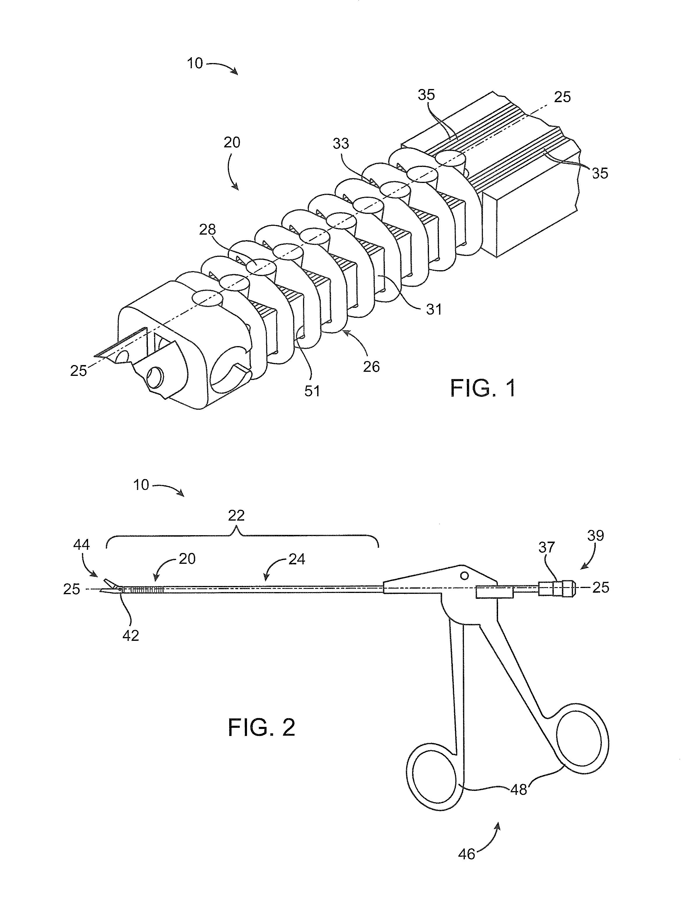
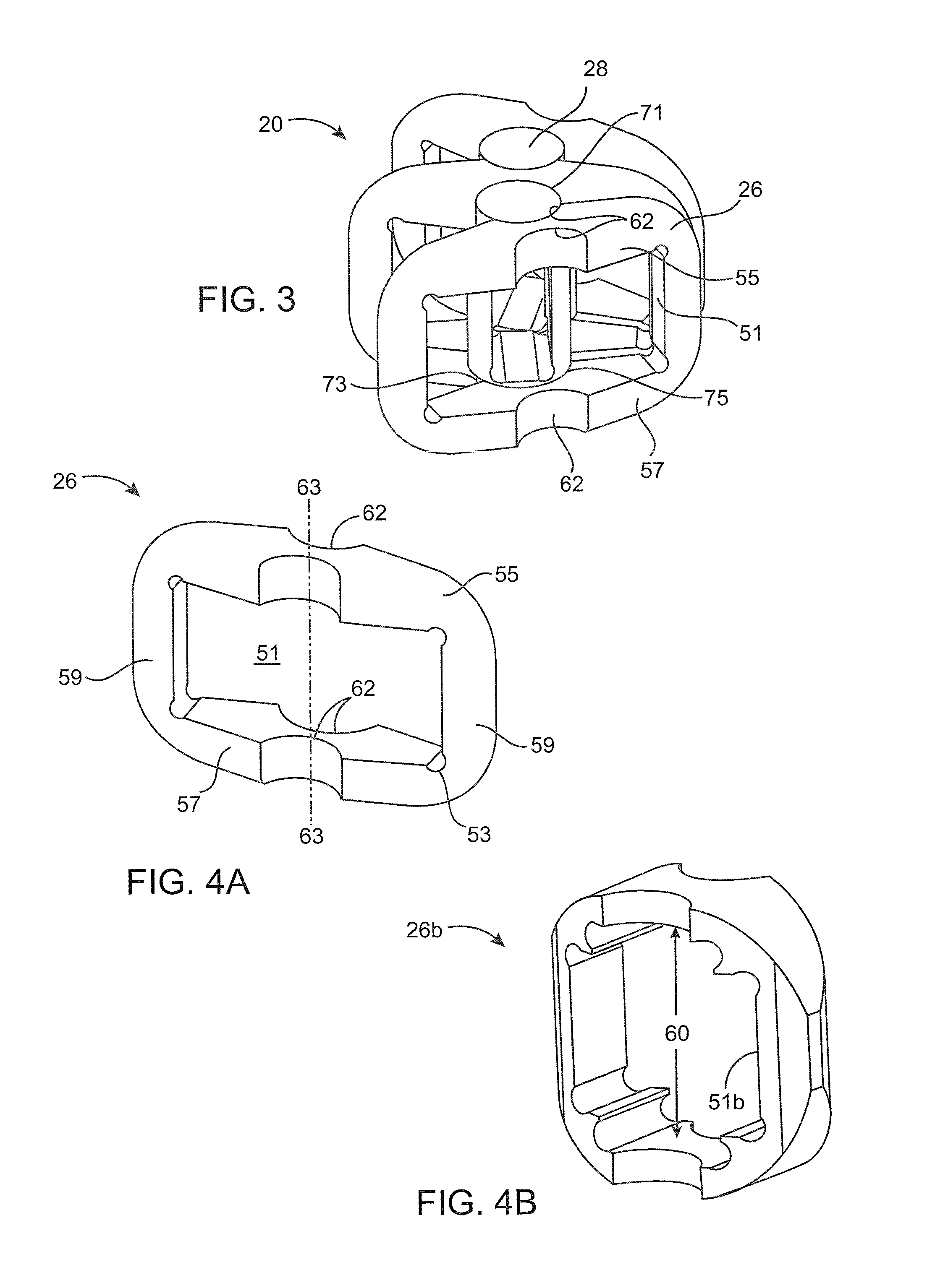
[0067]The herein invention may be embodied various medical devices that include an articulating or bendable portion formed from a plurality of pivot members that are arranged in succession and a related plurality of pivot assembly that pivotally connect adjacent ones of the plurality of pivot members.

[0068]A first embodiment of a medical device is illustrated in FIGS. 1 and 2 and designated generally by the reference numeral 10. The medical device, or instrument, 10 is particularly configured for intricate surgical procedures where a direct, straight path to a desired destination is unavailable. In particular, endoscopic surgeries typically require circumnavigation around particular areas within the human body in order to reach a desired location for treatment.

[0069]The device 10 includes an articulating shaft, or bendable portion, 20 of particular interest to the invention. The articulating shaft 20 is formed as a distal portion of an overall shaft 22 that also includes a proximal ...


PUM


Abstract

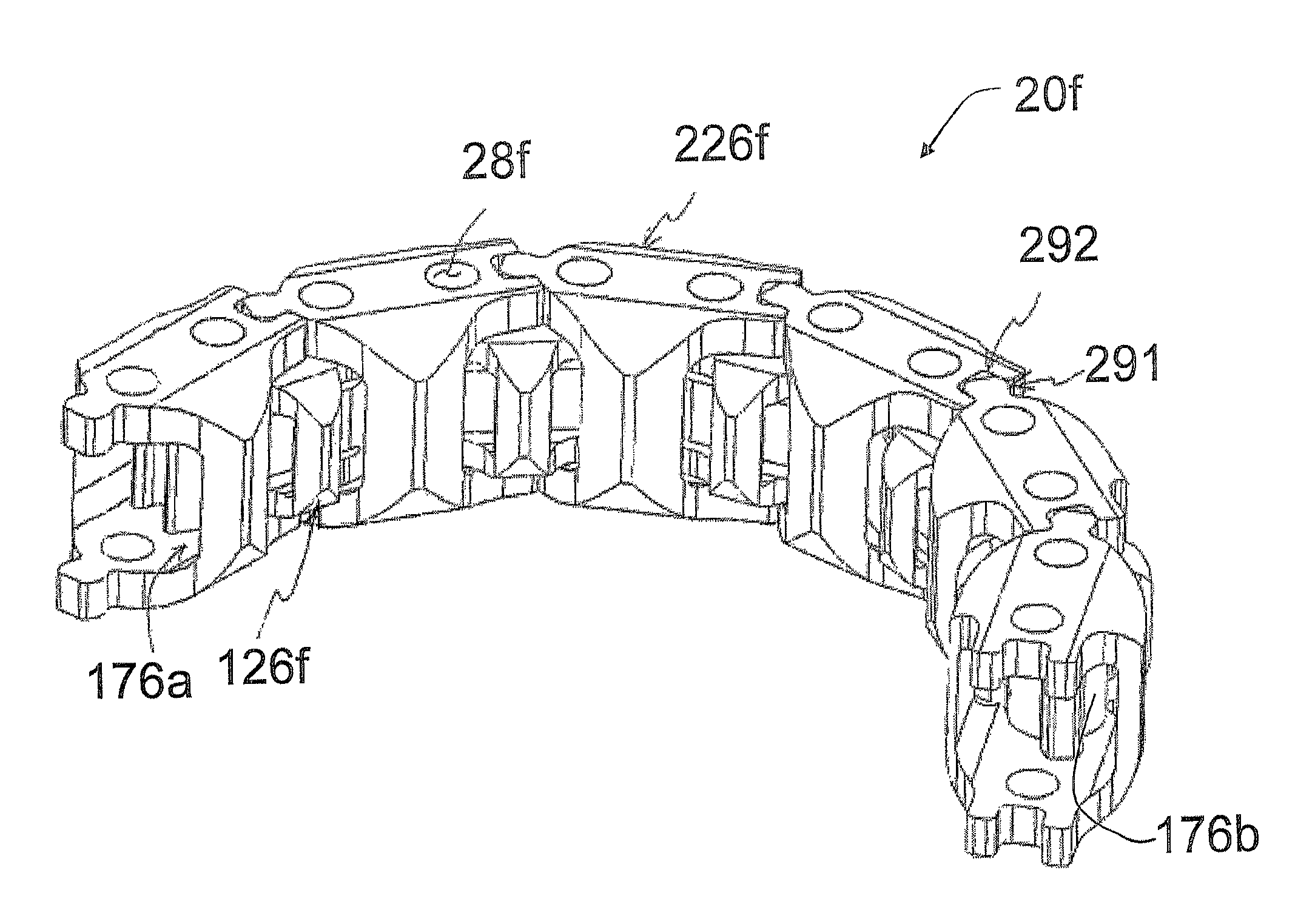
A medical device (10) includes an articulating shaft (20, 20a, 20b, 20c, 20d, 20e, or 20f) with a pair of slat assemblies (31, 33). By moving an articulator (37), the slat assemblies (31, 33) are configured to concurrently push while the other pulls in order to bend the articulating shaft (20). The articulating shaft (20) includes a series of pivot members (26, 26a, 26b, 26c, 26d, 126e and 226e, or 126f and 226f). The pivot members (26) may include inner links (126e, 126f) and outer links (226e, 226f) . A method for articulating a shaft of a medical device is also provided.

Description

RELATED APPLICATIONS[0001]This application is a continuation in part of U.S. patent application Ser. No. 11 / 211,834 filed on Aug. 25, 2005 and entitled “MEDICAL DEVICE WITH ARTICULATING SHAFT,” and claims priority of U.S. Provisional Patent Application Ser. No. 60 / 804,184 filed on Jun. 8, 2006 and entitled “METHOD OF CREATING A FLEXIBLE SHAFT,” the disclosures of both applications hereby being incorporated by reference in their entirety.BACKGROUND OF THE INVENTION[0002]1. Field of the Invention[0003]The invention relates generally to surgical devices and methods, and more particularly to shafts.[0004]2. Description of Prior Art and Related Information[0005]In various types of surgical procedures, particularly in endoscopy, a need exists for articulating, or bendable shafts. Such shafts are preferable, and often times necessary, for circumnavigating particular areas in the human body in order to reach a specific destination therein. Articulating shafts in the prior art include comple...

Claims


Application Information

Patent Timeline
Patent Type & Authority Patents(United States)
IPC IPC(8): A61B1/00
CPCA61B17/29A61B17/320016A61B2017/003A61B2017/00314A61B2017/00327A61B2017/2902A61B2017/2905A61B2017/291A61B2017/2927
Inventor PADGET, MARTINSKINLO, DAVIDWEISEL, THOMASCHU, LONGOPISARNWONGS, ROGER
Owner BANNERMAN BRETT
Learn More