
Articulator and optical detection cursor positioning device

a cursor positioning and articulator technology, applied in the field of mouse-type input devices, can solve the problems of limiting the use of such devices, damage to the device, and none of these types of devices have been successfully sealed, and achieve the effect of pointing the cursor easily and quickly

Inactive Publication Date: 2005-02-08
BOWEN JAMES H
View PDF26 Cites 25 Cited by
  • Summary
  • Abstract
  • Description
  • Claims
  • Application Information

AI Technical Summary

Benefits of technology

It is therefor the primary objective of this invention to provide a cursor positioning device that can be sealed if the environment requires sealing, that can withstand harsh use, and can position the cursor easily and quickly.
The key and articulator interrupters block optical beams for key and cursor positioning detection, thus eliminating any physical contact or force from the user from the key or articulator to any detection components. The cursor positioning device being a positioning interrupter disposed between an inner and outer ring of optical emitters and detectors, whereas depending on the amount of movement and the position of movement by the interrupter emission is varied between a particular pair of emitters and detectors, that point is the direction of cursor movement.
It is also a further object of this invention when a key or articulator is in the most depressed position the key cap or articulator is against the cursor positioning device top surface protecting all internal parts from pressure, or force from harsh use or a vandals blow.
It is also a further object of this invention to allow the cursor positioning device to be easily cleaned.

Problems solved by technology

None of these types have been successfully sealed because if a contaminate gets on the ball or wheel it is forced past the seal and into the rotating mechanism.
And if severe strain is applied will damage the sensor because normal operation requires contact with the sensor.
These are contact sensitive type devices whereas sharp object will damage the device.
Harsh environments or on irregular surfaces limit the use of such devices.
These types of input devices are not user-friendly because of limited angular positioning of the cursor.

Method used


Image

  • Articulator and optical detection cursor positioning device
  • Articulator and optical detection cursor positioning device
  • Articulator and optical detection cursor positioning device

Examples


Embodiment Construction

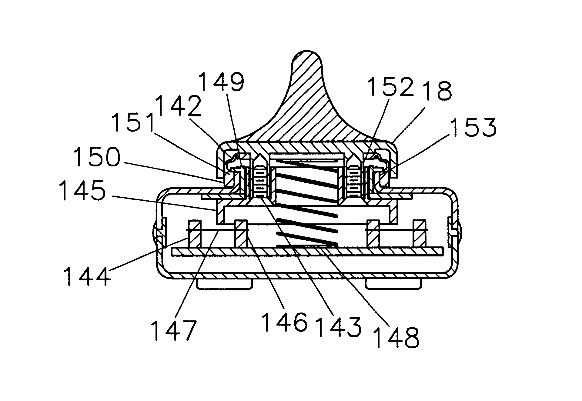
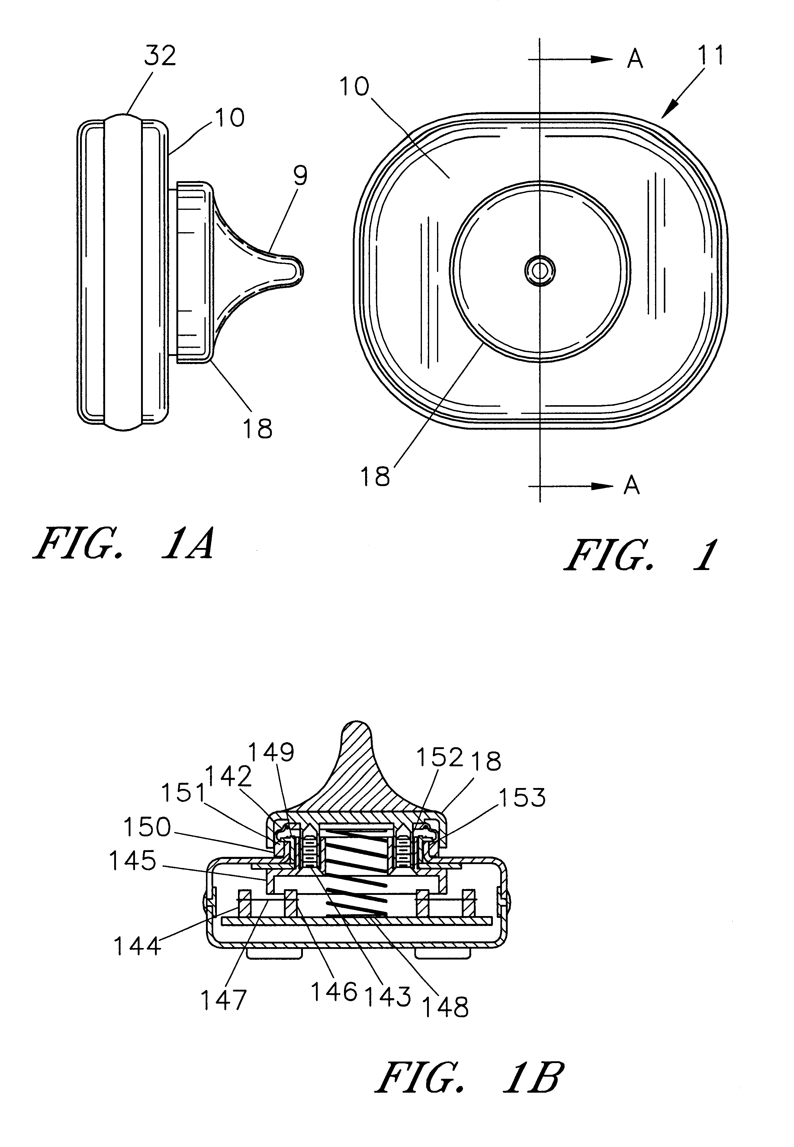
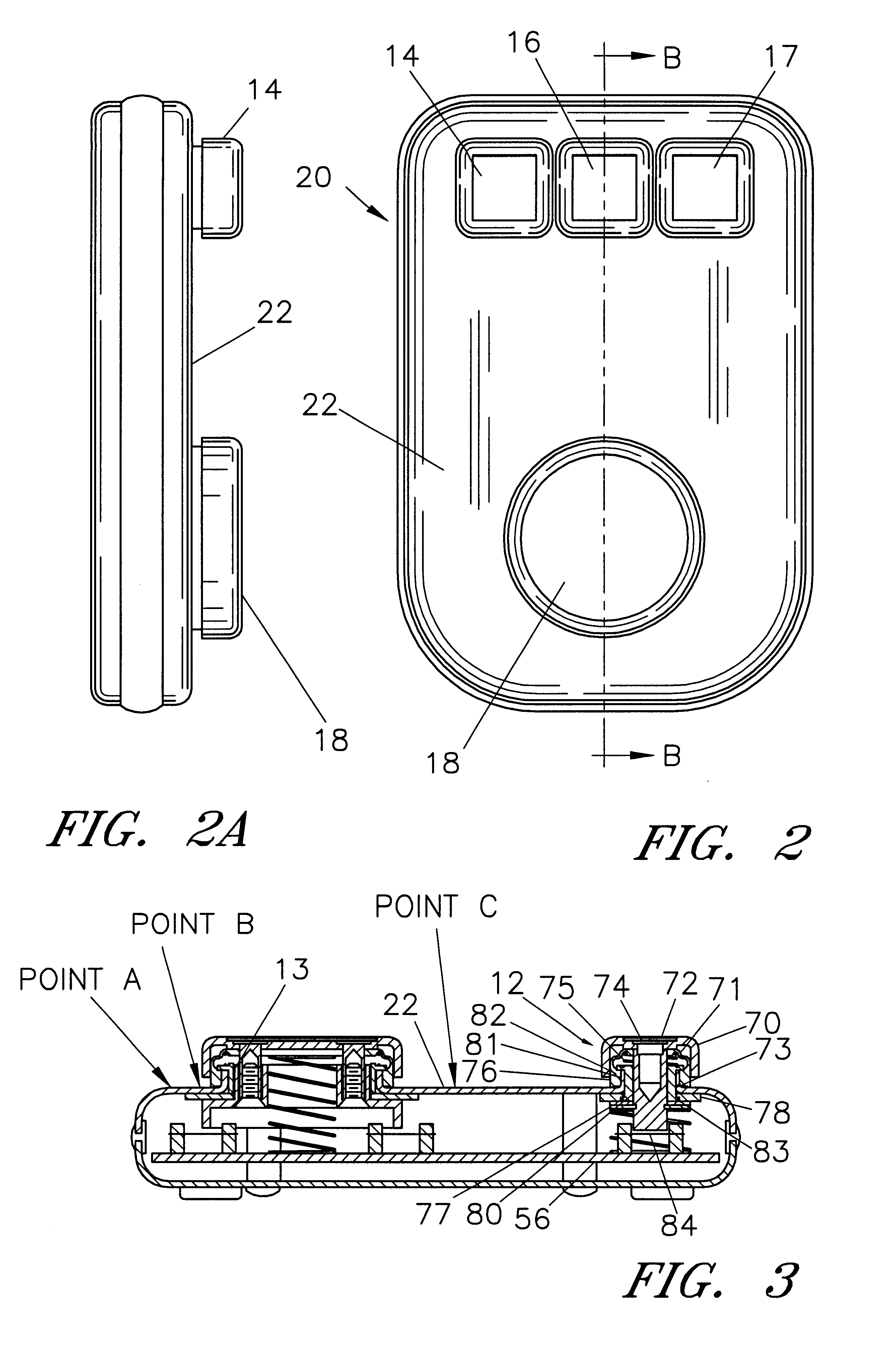
Referring now to the drawings, in which the same reference numeral indicates the same element in the various figures, FIG. 1 shows a top surface 10 of cursor positioning device 11 and cursor articulator 18 used to position a cursor. Articulator top 9 shows a shape that can be used by one finger to position the cursor, and stops a vandal from hitting articulator 18 with a fist. Cursor positioning device 11 is a full function mouse in as much as all control of the cursor and related functions are preformed with cursor articulator 18. Clicking is preformed by down up movement, speed of down up movement and location of down up movement making up a signature for a single or double click or drag as required for cursor functions. FIG. 1A is a side view of FIG. 1 with top surface 10, side view of cursor articulator 18 and peripheral seal 32. FIG. 1B is a cross section view at A—A through the mouse in FIG. 1. Cursor articulator 18 is retained by fasteners 143 being threadably received into p...


PUM


Abstract

A cursor positioning device that can be sealed if the environment requires sealing, that can withstand harsh use, and can position the cursor easily and quickly. In operation the where the operator places their fingers on the positioning articulator and rocks or slides the articulator in the direction they want the cursor to move. And with movement signatures do single and double clicks, and character strings to the host computer, either through the mouse port or the keyboard port. The key and articulator interrupters block optical beams for key and mouse like positioning thus eliminating any physical contact or force from articulator to detecting optics. Cursor position is positioned by an interrupter disposed in a ring of optical emitters and detectors, whereas depending on the position of movement by the positioning interrupter emission is blocked, or partially blocked, between a particular pair or pairs of emitters and detectors, that particular pair or pairs being the direction of cursor movement. The amount of articulator movement is the distance the cursor moves.

Description

BACKGROUND OF THE INVENTION1. Field of the InventionThe present invention generally relates to mouse type input devices for computers that need data entry in office and harsh environments, both indoor and outdoor, and in public access areas.2. Description of the Prior ArtPrior art mouse type input devices fall into five basic category types: rotating mechanism, strain mechanism, electronic touch positioning, optical surface detecting and switch.Rotating mechanisms include the most common and widely used whereas a ball is in contact with a surface, either a hand or desk, and the relative movement of the hand or distance traveled over a surface rotates either an optical counter or potentiometer. Other variations include joysticks and wheels that are moved and in turn rotate an optical counter or potentiometer. None of these types have been successfully sealed because if a contaminate gets on the ball or wheel it is forced past the seal and into the rotating mechanism. And just the fac...

Claims


Application Information

Patent Timeline
IPC IPC(8): G06F3/033
CPCG06F3/0338
Inventor BOWEN, JAMES H.
Owner BOWEN JAMES H
Learn More