
System and method to identify and communicate congested flows in a network fabric

a network fabric and flow technology, applied in the field of system and method to identify and communicate congested flows in the network fabric, can solve the problems of not realizing ideal behavior, specifically limited to this application, and dllp not allowing this mechanism to scale, and achieves a comprehensive and elegant solution

Active Publication Date: 2010-03-02
CALLAHAN CELLULAR L L C
View PDF7 Cites 8 Cited by
  • Summary
  • Abstract
  • Description
  • Claims
  • Application Information

AI Technical Summary

Benefits of technology

This solution enables precise identification and communication of congested paths, reducing unnecessary packet holding and improving network throughput and latency by ensuring only packets destined for congested paths are delayed, thereby optimizing network performance.

Problems solved by technology

However, because of a number of factors, this ideal behavior is not realizable.
For instance, if the switch receives packets on several of its input ports destined for the same output port, the switch must store the information internally, since it cannot transmit all of these different packets of information simultaneously to the same output port.
This mechanism is very effective to communicate congestion in one switch to the adjacent switch, however, it is specifically limited to this application.
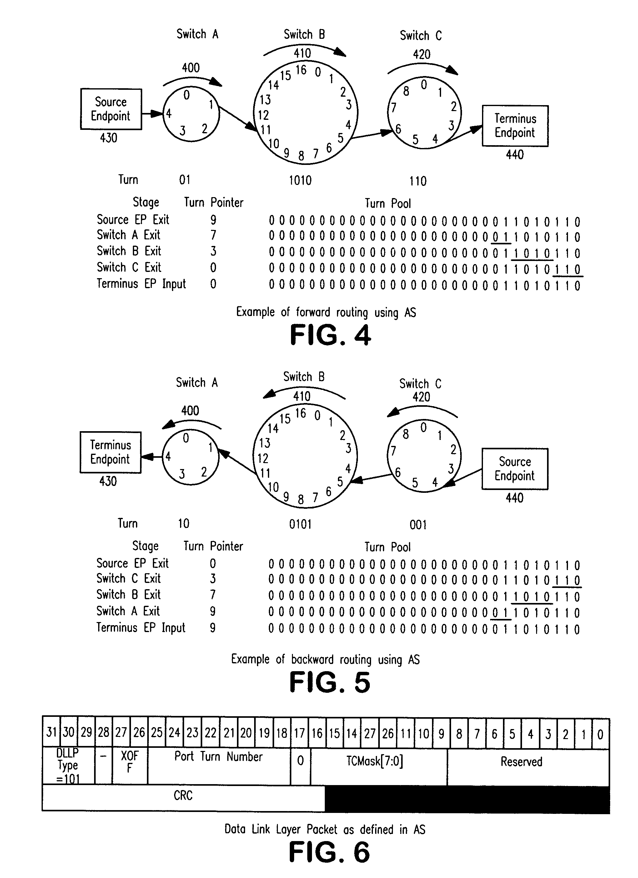
The format of a DLLP does not allow this mechanism to scale to identify congested paths through the entire fabric.
Thus, while congestion is reduced since traffic is no longer being sent to the congested port, there are undesirable effects of this scheme.
Similarly, any packet in upstream switch A destined to be transmitted via any output port in downstream switch C except output port 5 will unnecessarily be held in upstream switch A. This reduces the throughput of the fabric and increases latency.

Method used


Image

  • System and method to identify and communicate congested flows in a network fabric
  • System and method to identify and communicate congested flows in a network fabric
  • System and method to identify and communicate congested flows in a network fabric

Examples


Embodiment Construction

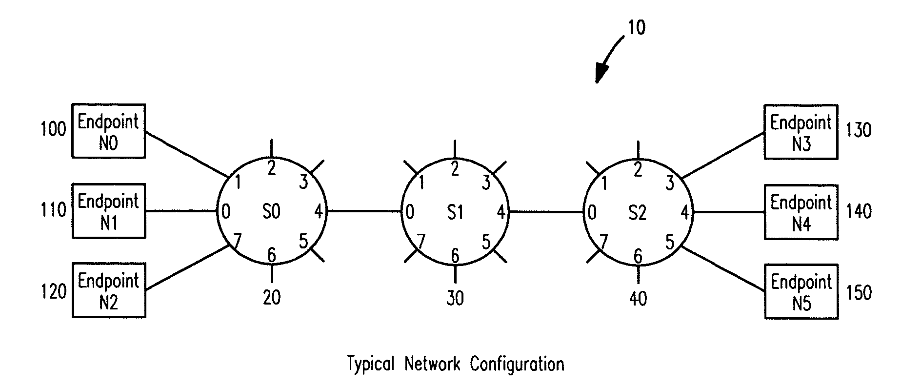
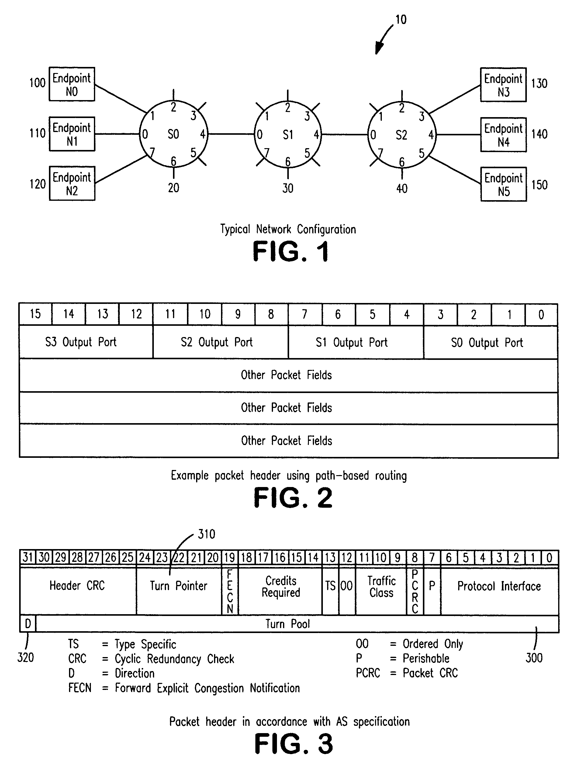
[0018]Within computer networks, systems, also known as fabrics, are designed that allow multiple nodes, or endpoints to communicate with one another. FIG. 1 illustrates a configuration used in the creation of such a fabric. Fabric 10 is comprised of a number of devices, or nodes, that are interconnected to one another. These devices, broadly known as switches, are capable of receiving packets of information via a plurality of input ports and then transmitting these packets via a plurality of output ports, preferably via an output port that is different than the input port. When a number of these are connected together, it is possible to create a fabric whereby multiple endpoints are able to communicate with each other via the various paths that are established by the switches. Within fabric 10, three switches, 20, 30 and 40 are shown. Most fabrics are more complex than this example, with additional switches connected to the unused outputs of switches 20,30, and 40. There is no theor...


PUM


Abstract

The invention provides a system and method for identifying and communicating congested paths throughout a network fabric. Briefly, the present invention augments the congestion management mechanism defined in ASI to allow for the communication of congested paths through the fabric, rather than the simple congested output port notification supported today through the use of DLLPs. Further, it also uses the communication mechanisms already defined in the ASI specification to implement this additional capability. Specifically, the present invention uses Transaction Layer Packets (TLPs) to communicate the information concerning congested flows throughout the network. This packet type allows the inclusion of much more information than DLLPs, allowing a more comprehensive and elegant solution to the issue of congestion management in an Advanced Switching network fabric.

Description

BACKGROUND OF THE INVENTION[0001]In computer networks, information is constantly being moved from a source to a destination, typically in the form of packets. In the simplest situations, the source and destination are directly connected and the packet of information passes from the source to the destination, without any intermediate stages. However, in most networks, there are at least one, if not multiple, intermediate stages between the source and the destination. In order for the information to move from the source to the destination, it must be routed through a set of devices that accept the packet and pass it along a predetermined path toward the destination. These devices, referred to generically as switches, are typically configured to accept packets from some number of input ports and transmit that information to an output port, which was selected from a plurality of ports. Often, ports are capable of both receiving and transmitting, such that the input and output ports are ...

Claims


Application Information

Patent Timeline
Patent Type & Authority Patents(United States)
IPC IPC(8): H04L12/26H04L12/28H04L12/56
CPCH04L45/34H04L47/10H04L47/11H04L47/122H04L47/263H04L47/30H04L47/32H04L49/50
Inventor MAYHEW, DAVID
Owner CALLAHAN CELLULAR L L C
Learn More