Method and apparatus for precursively controlling energy during coaptive tissue fusion

a coaptive tissue and energy control technology, applied in the field of precursive control energy during coaptive tissue fusion, to achieve the effect of reducing the risk of recurren

Active Publication Date: 2010-03-16
CONMED CORP
View PDF32 Cites 166 Cited by
  • Summary
  • Abstract
  • Description
  • Claims
  • Application Information

AI Technical Summary

Benefits of technology

[0012]The present invention fuses and seals tissue by determining a straightforward precursor fusion condition during the progress of the tissue sealing procedure. The precursor fusion condition establishes the conditions for terminating the delivery of electrical energy. The precursor fusion condition is relatively easily sensed and determined, and the precursor condition is used in a straightforward manner to control energy application without requiring complex calculations, feedback power control loops, or energy modulation techniques. Furthermore, even though the precursor fusion condition is not predictably and reliably related to tissue impedance, the precursor fusion condition nevertheless predicts conditions under which a very effective seal is achieved in different types of tissues. The present invention permits a prior art electrosurgical generator and a prior art tissue sealing handpiece to be used together as a tissue fusion apparatus, thereby avoiding the necessity to use a separate and expensive energy generator designed specifically for tissue sealing purposes. Tissue seals which are equally or more effective are typically obtained in considerably shorter times, compared to those tissue seals obtained by known and commercially available prior art tissue sealing devices.

Problems solved by technology

Furthermore, even though the precursor fusion condition is not predictably and reliably related to tissue impedance, the precursor fusion condition nevertheless predicts conditions under which a very effective seal is achieved in different types of tissues.

Method used


Image

  • Method and apparatus for precursively controlling energy during coaptive tissue fusion
  • Method and apparatus for precursively controlling energy during coaptive tissue fusion
  • Method and apparatus for precursively controlling energy during coaptive tissue fusion

Examples


Embodiment Construction

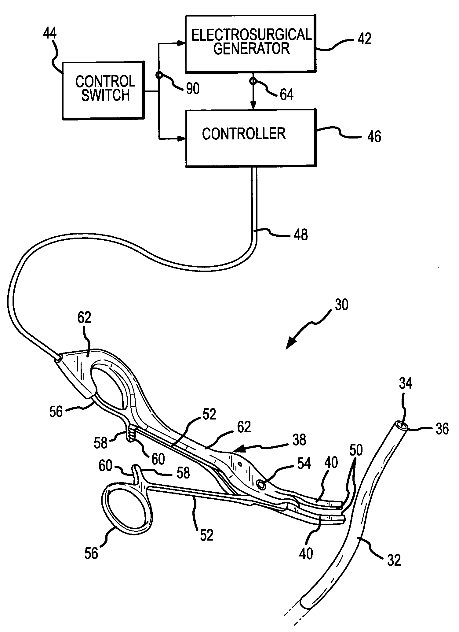
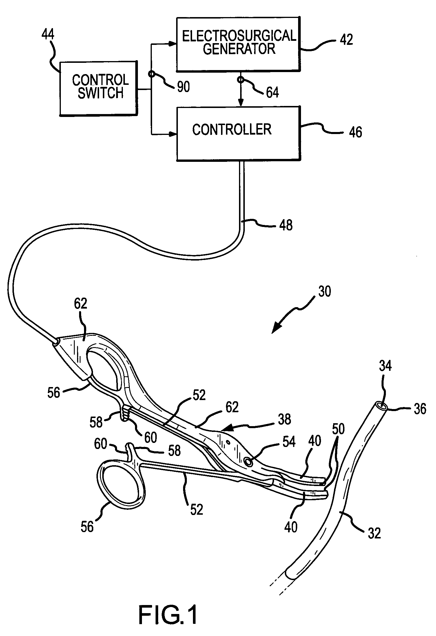
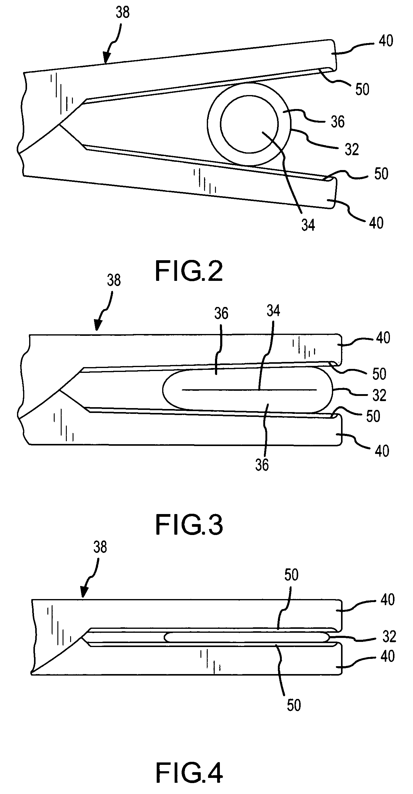
[0030]A coaptive biological tissue sealing apparatus 30, the use of which also exemplifies the practice of a method of coaptively sealing biological tissue, both of which incorporate the present invention, is shown in FIG. 1. The coaptive tissue sealing apparatus 30 is used to permanently close a lumen, duct, passageway or chamber formed in and surrounded by the biological tissue. The biological tissue is exemplified in FIG. 1 (and FIGS. 2-4) by a biological vessel 32, such as an artery or vein. Other examples of biological tissue which may be permanently sealed by use of the present invention include fallopian tubes, bile ducts, tissue surrounding an aveoli or air sac in the lung, the colon or bowel, and any other structure where ligation might otherwise be performed.

[0031]For the present purposes of describing preferred embodiments of the sealing apparatus 30 and the coaptive sealing method which incorporate the present invention, the vessel 32 will be used as an example of the bi...


PUM


Abstract

A sidewall of biological tissue which surrounds and defines an opening in the tissue is sealed or fused to occlude the opening by compressing apposite sidewall portions and applying sufficient energy to cause the fibers of the compressed apposed sidewall portions to intertwine and fuse with one another to form a permanent seal. The energy application is controlled by detecting a precursor fusion condition while applying the energy and before sufficient energy has been applied to achieve an adequate seal. The application of energy is terminated in a time-delayed relationship to the detection of the precursor fusion condition such that sufficient energy has been applied to achieve an effective seal. The precursor fusion condition is detected upon the peak RF current delivered to the tissue remaining below a threshold value for a threshold time.

Description

[0001]The present invention relates to fusing or sealing biological tissue to permanently occlude a lumen, duct, passageway or chamber formed in and surrounded by the tissue. More particularly, the present invention relates to a new and improved coaptive sealing apparatus and method which straightforwardly controls the energy applied to the tissue based on a precursive fusion condition to reliably and rapidly achieve an effective seal, without the use of complicated, expensive and ineffective energy control and feedback techniques.BACKGROUND OF THE INVENTION[0002]Tissue fusion has been used in medical procedures for many decades, primarily to prevent bleeding from severed blood vessels. One age-old technique of fusing tissue involves heat application to cauterize vessels. More recent techniques involve the application of electrosurgical electrical energy to tissue to create the heat necessary for tissue fusion. The electrical energy may be applied in an obliterative or a coaptive ma...

Claims


Application Information

Patent Timeline
Patent Type & Authority Patents(United States)
IPC IPC(8): A61B18/14
CPCA61B18/1442A61B2018/00005A61B2018/0063A61B2018/00702A61B2018/00827
Inventor MCGREEVY, FRANCIS T.PAVLOVSKY, KATHERINE R.
Owner CONMED CORP
Why Eureka
Try Eureka