Target detection apparatus and system

a target detection and target technology, applied in direction finders using radio waves, distance measurement, instruments, etc., can solve the problems of requiring frequent maintenance, requiring a large signal processing cost, and affecting the performance of the target detection apparatus

Inactive Publication Date: 2010-03-16
FUJITSU LTD
View PDF31 Cites 29 Cited by
  • Summary
  • Abstract
  • Description
  • Claims
  • Application Information

AI Technical Summary

Benefits of technology

[0028]The first problem of the present invention is to provide a low-cost target detection apparatus or a target detection system appropriate for an exposure environment such as an outdoor area, etc.

Problems solved by technology

Therefore, frequent maintenance is required.
Furthermore, a change in the optical characteristic of a peripheral environment depending on the time can be a serious problem in guaranteeing the performance.
On the other hand, the detection device of a radio system such as a radar device, etc. is advantageous in resistance to environment, but there is the problem in performance because a target is to be localized normally as a point in the polar coordinate system.
A radar device having an array antenna can calculate the angles of a plurality of targets, but is a narrow angle measurement range per device, and requires a large signal processing cost.
However, the above-mentioned conventional target detection apparatus has the following problems.(1) A detection device of an optical system such as a laser device, etc. is subject to an influence of an ambient environment, and it is difficult to guarantee the performance when it is mounted outdoors.
However, since the parts constituting a radar device are expensive, it is desired to realize an angle measurement in a wide range using the smallest possible number of devices.
Therefore, with an increasing number of targets for the two detection devices, a higher calculating cost is required to remove detection errors, and there immediately occurs a problem if the number of devices is reduced.(3) When a large number of targets intrude into a monitor area, it is desired to localize the position of each target as a point in the orthogonal coordinate system or the polar coordinate system to correctly discriminate the targets.
However, it is very difficult to perform the process of discriminating a number of targets in a predetermined time using only an autonomous position meter in the conventional detection device in an optical system or a radar system.

Method used


Image

  • Target detection apparatus and system
  • Target detection apparatus and system
  • Target detection apparatus and system

Examples


Embodiment Construction

[0062]The best modes for embodying the present invention are described below in detail by referring to the attached drawings.

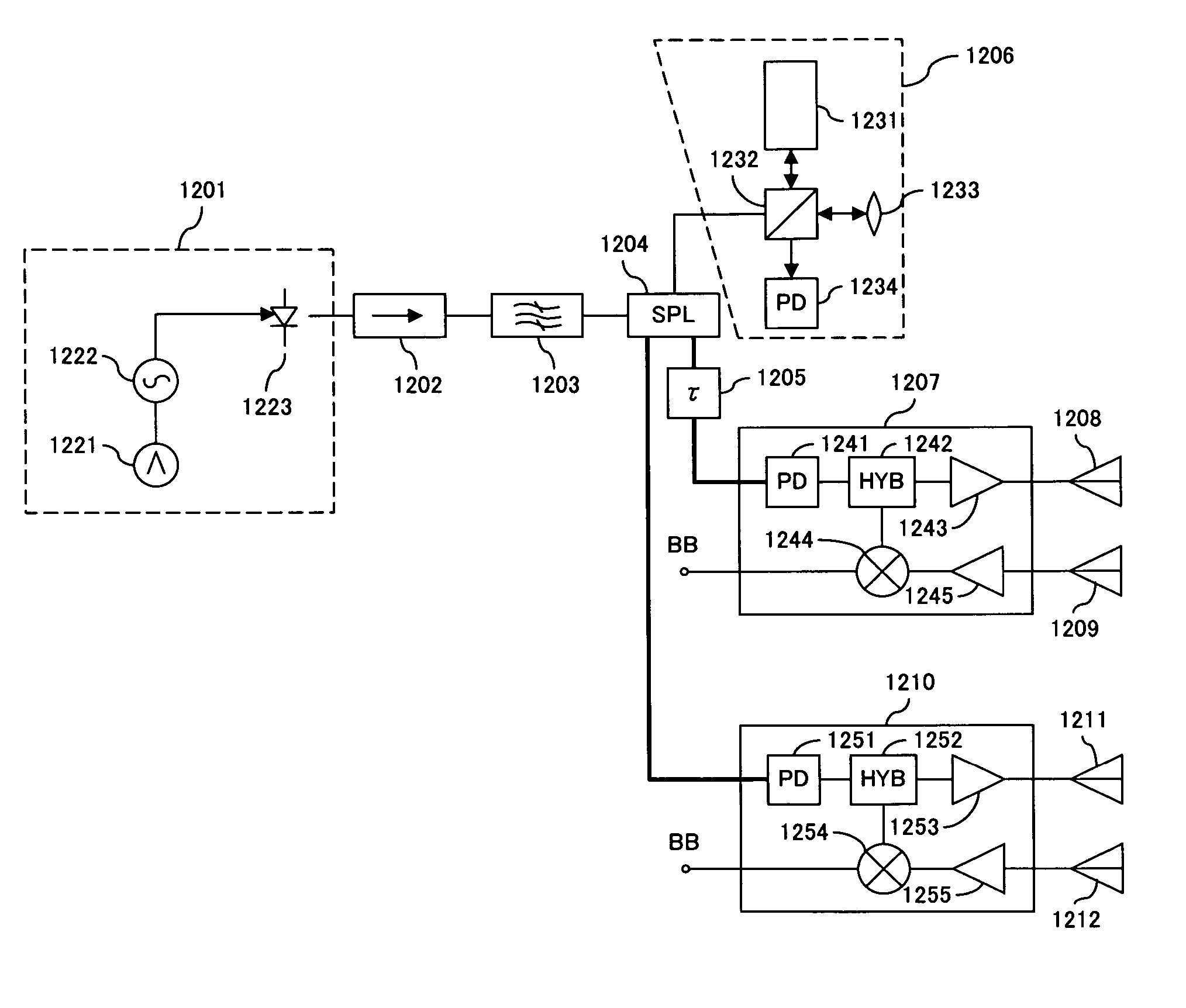
[0063]FIG. 2A shows the principle of the target detection apparatus according to the present invention. The target detection apparatus shown in FIG. 2A comprises a transmission / reception device 101, sensors 102-1 through 102-m, and a switch device 103. The transmission / reception device 101 generates a transmission signal for detection of a target, and extracts the distance information about the target from a received signal. The sensors 102-1 through 102-m transmits a transmission signal to each of the different angle ranges, receives a signal reflected by the target, and transfers the received signal to the transmission / reception device 101. The switch device 103 switches the connection between the transmission / reception device 101 and the sensors 102-1 through 102-m in a time division manner.

[0064]The sensors 102-1 through 102-m can be, for example, an anten...


PUM


Abstract

A target detection apparatus that includes a transmission / reception device for generating a transmission signal for detection of a target, and extracting distance information about the target from a received signal; a number of sensors each of which transmits the transmission signal to respective different angle ranges, receives a signal reflected by the target, and transfers the received signal to the transmission / reception device; and a switch device for switching in a time division manner a connection between the transmission / reception device and one of the sensors to a connection between the transmission / reception device and another one of the sensors, where the switch device selects a first of the sensors for transmitting the transmission signal in a time slot and a second of the sensors for receiving the signal reflected by the target in the time slot.

Description

CROSS-REFERENCE TO RELATED APPLICATIONS[0001]This patent application is a continuation in part application of the previous U.S. patent application, titled “TARGET DETECTION APPARATUS AND SYSTEM,” filed on Apr. 7, 2006, application Ser. No. 11 / 400,254, now abandoned, herein incorporated by reference.BACKGROUND OF THE INVENTION[0002]1. Field of the Invention[0003]The present invention relates to an apparatus and a system for detecting a target such as a person, an animal, an object, etc. intruding into a monitor area.[0004]2. Description of the Related Art[0005]There have conventionally been a camera, a laser device, a monopulse radar device, etc. for detecting any number of targets T intruding into a predetermined monitor area as shown in FIG. 1A. The position of a target T is expressed by, for example, (x, y) in the Cartesian coordinate system (orthogonal coordinate system), and (r, θ) in the polar coordinate system.[0006]However, since the detection device of an optical system such...

Claims


Application Information

Patent Timeline
Patent Type & Authority Patents(United States)
IPC IPC(8): G01S13/06G01S15/06G01S17/06G01S13/00G01S17/00G01S15/00G01S17/04G01S17/87
CPCG01S13/003G01S13/48G01S17/87G01S13/886G01S17/026G01S13/878G01S17/04
Inventor SHIRAKAWA, KAZUO
Owner FUJITSU LTD
Why Eureka
Try Eureka