Rolling knee support with detachable knee pad

Active Publication Date: 2010-03-23
NOMIS LLC
View PDF34 Cites 26 Cited by
  • Summary
  • Abstract
  • Description
  • Claims
  • Application Information

AI Technical Summary

Problems solved by technology

Because the knee pad is permanently attached to the base, the entire rolling knee support must be replaced if the base and / or the knee pad becomes worn or damaged.

Method used


Image

  • Rolling knee support with detachable knee pad
  • Rolling knee support with detachable knee pad
  • Rolling knee support with detachable knee pad

Examples


Embodiment Construction

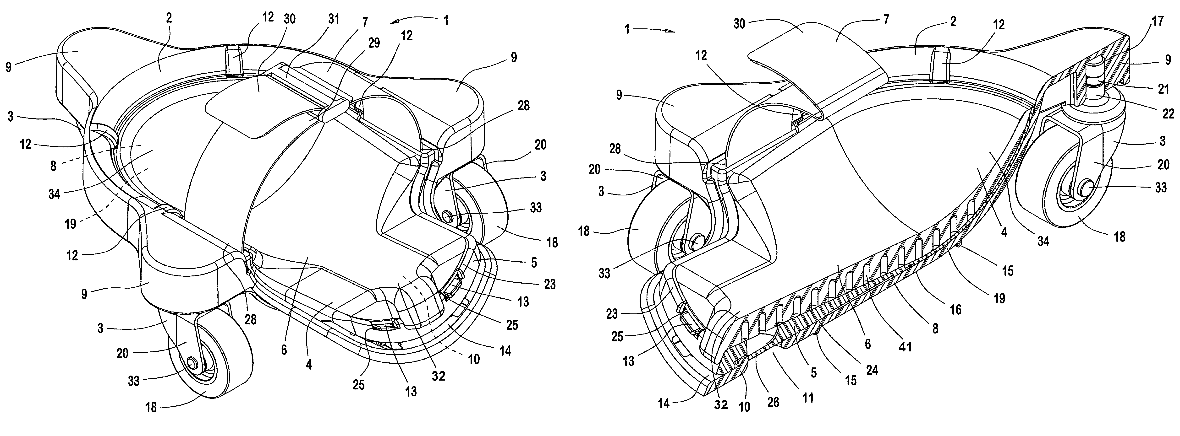
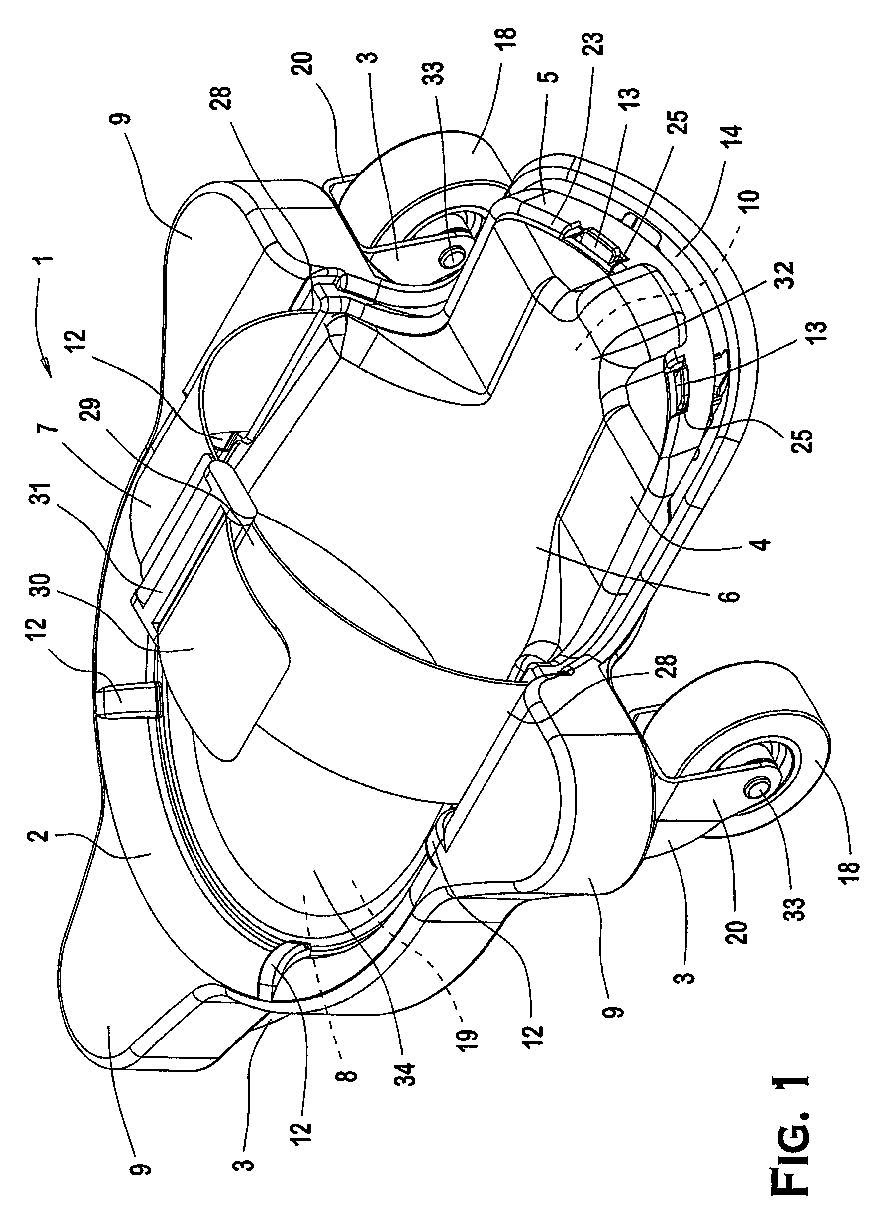
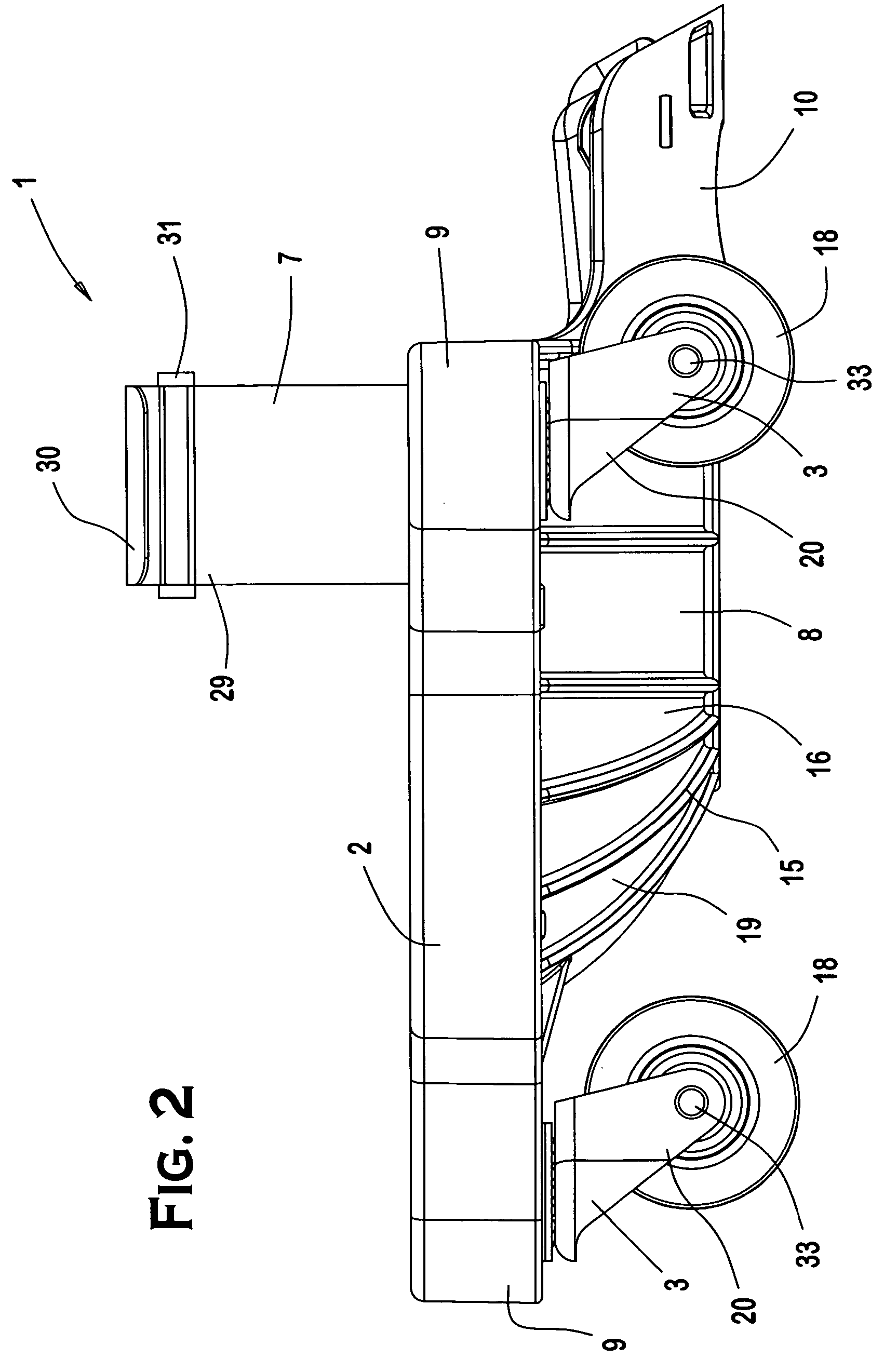
[0016]FIGS. 1-3 show a rolling knee support 1 according to the invention. As shown in FIG. 1, the rolling knee support 1 comprises a base 2 with a plurality of casters 3. A knee pad 4 is detachably mounted to the base 2. The knee pad 4 comprises a shell 5 and a cushion 6. A strap 7 is attached to the shell 5. The rolling knee support 1 is secured to a wearer's knee area by the strap 7.

[0017]Each of the individual elements of the rolling knee pad 1 will now be described in greater detail. As shown in FIGS. 1-3, the base 2 includes a knee pad receiving portion 8 and roller attachment members 9. The knee pad receiving portion 8 is substantially concave in shape and consists of a knee support area 19 and a shin support area 10. The shin support area 10 extends from the knee support area 19 and has a release aperture 11 formed therein, as best shown in FIG. 3. It will be appreciated by those skilled in the art that the knee pad receiving portion 8 may alternatively be formed without the ...


PUM


Abstract

A rolling knee support comprises a base with a detachable knee pad. The base includes a knee pad receiving portion and roller attachment portions. Each of the roller attachment portions has a caster mounted thereto. The knee pad is detachably mounted to the knee pad receiving portion. A strap extends from the rolling knee support for attachment of the rolling knee support to a wearer's knee area. An outer cover may be placed on the knee pad when the knee pad is detached from the rolling knee support.

Description

CROSS-REFERENCE TO RELATED APPLICATIONS[0001]This application is a continuation-in-part of U.S. patent application Ser. No. 11 / 138,610, filed May 26, 2005 now abandoned.FIELD OF THE INVENTION[0002]The invention generally relates to a rolling knee support and, more particularly, relates to a rolling knee support having a detachable knee pad with an outer cover.BACKGROUND OF THE INVENTION[0003]Knee pads are designed to cushion and protect a wearer's knee area when the wearer is kneeling on a support surface. Some types of knee pads comprise only a cushion to protect the wearer's knee area while other types of knee pads comprise a cushion that directly or indirectly contacts the wearer's knee area and a shell that contacts the support surface. Still other types of knee pads have a base to facilitate rolling the knee pad along the support surface. These rolling knee supports are designed to protect the wearer's knee area while also providing the wearer with a degree of mobility while th...

Claims


Application Information

Patent Timeline
Patent Type & Authority Patents(United States)
IPC IPC(8): A41D13/00A41D13/06A41D27/12A63C17/00
CPCA63B71/1225A63C17/0026A63B2071/125
Inventor LEGENSTEIN, MARK P.
Owner NOMIS LLC
Why Eureka
Try Eureka