Connector with an anti-unlocking system

a technology of anti-unlocking system and connector, which is applied in the direction of electrically conductive connections, coupling device connections, instruments, etc., can solve the problems of providing an obstacle to and achieve the effect of reducing the risk of untimely unlocking of the locking sleeve and reliably guaranteeing the connection

Inactive Publication Date: 2010-03-23
RADIALL SA
View PDF33 Cites 120 Cited by
  • Summary
  • Abstract
  • Description
  • Claims
  • Application Information

AI Technical Summary

Benefits of technology

[0005]There is therefore a need for a novel type of connector that is capable of reliably guaranteeing the connection while reducing any risk of untimely unlocking of the locking sleeve.

Problems solved by technology

Thus, implementing such a brake ring serves to provide an obstacle to unwanted unlocking of the locking sleeve.

Method used


Image

  • Connector with an anti-unlocking system
  • Connector with an anti-unlocking system
  • Connector with an anti-unlocking system

Examples


Embodiment Construction

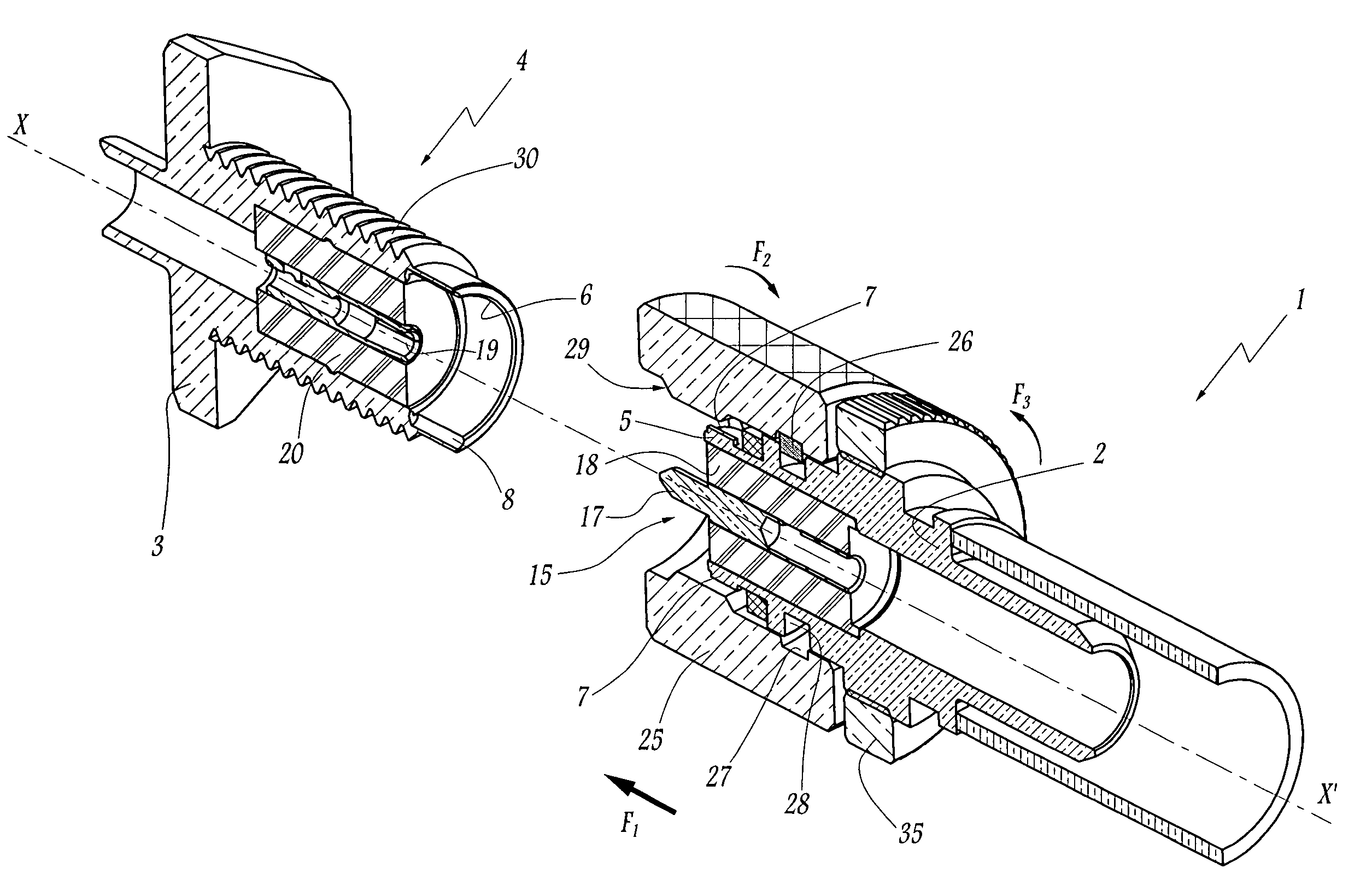
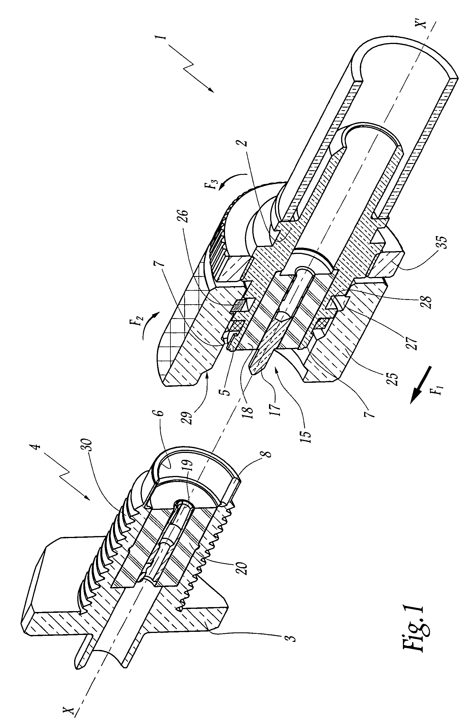
[0031]A connector of the invention, as shown in FIG. 1, is given overall reference 1 and comprises a body 2 for plugging in a plugging axis X-X′ in the body 3 of a complementary connector given overall reference 4. In the example shown, the functional end 5 of the body 2 possesses a male shape generally in the form of a cylinder of revolution that is designed to be engaged by moving in translation into a housing of complementary shape 6 provided in the body 3 of the complementary connector 4. Given that the housing 6 and the end 5 are in the form of cylinders of revolution, the connector 1 includes means for preventing the body 2 from turning relative to the body 3, said means being in the form of keys 7 arranged on the outside surface of the active end 5 and designed to engage in complementary grooves 8 arranged in the housing 6 of the complementary connector 4.

[0032]In order to perform its function of connecting conductors together, electrically and / or optically, the connector 1 f...


PUM


Abstract

A connector comprising:a body for plugging in or on the body of a complementary connector along a plugging axis X-X′;connection means for co-operating with complementary connection means of the complementary connector so as to connect together electrical or optical conductors; anda locking sleeve that surrounds the body of the connector and that is adapted to co-operate with the body of the connector and with locking means provided by the complementary connector in such a manner as to block relative movement between the connector and the complementary connector in the plugging direction, the locking sleeve being movable in rotation about the axis relative to the body of the connector between an unlocking position in which the connectors can be separated and a locking position in which the connectors cannot be separated;wherein the connector includes a brake ring that co-operates with the body of the connector by being movable at least in rotation about the axis between a braking position in which the ring opposes any turning of the locking sleeve and a disengaged position in which the ring does not oppose any turning of the locking sleeve.

Description

FIELD OF THE INVENTION[0001]The present invention relates to the technical field of connectors used for making easily-separable connections between conductors of an electric and / or optical cable and a system or another electric and / or optical cable.[0002]The invention relates more particularly to the field of connectors in which connection with a complementary connector is performed along a plugging axis, the connectors thus being coupled together or uncoupled by a movement in translation parallel to the plugging axis.BACKGROUND OF THE INVENTION[0003]In order to guarantee a certain amount of reliability for the connections made and avoid any disconnection, such connectors are fitted with a locking sleeve that is designed to co-operate with locking means provided by the complementary connector. Thus, the locking sleeve can make use of a bayonet locking system or may indeed include a thread for co-operating with a complementary thread of the complementary connector. Such a locking sle...

Claims


Application Information

Patent Timeline
Patent Type & Authority Patents(United States)
IPC IPC(8): H01R4/38
CPCH01R13/622H01R13/639G02B6/3825G02B6/3891G02B6/3894G02B6/3897
Inventor BERTHET, VINCENT
Owner RADIALL SA
Why Eureka
Try Eureka