Insulation for baking chambers in a multi-deck baking oven

a multi-deck baking oven and baking chamber technology, applied in baking, food processing, domestic heating details, etc., can solve the problem that the insulating material of conventional insulating layers takes a long time to heat up and cool down, and achieve the effect of reducing the heat flow ra

Active Publication Date: 2010-03-30
MOFFAT
View PDF21 Cites 14 Cited by
  • Summary
  • Abstract
  • Description
  • Claims
  • Application Information

AI Technical Summary

Benefits of technology

[0008]In a first aspect of the present invention, there is provided a multi-deck baking oven including: a housing and at least two baking chambers located within the housing, adjacent baking chambers being separated by an insulating layer, at least one of the insulating layers including a hollow partition, wherein each insulating layer dampens the rate of heat flow between the adjacent baking chambers.
[0011]A fundamental difference between the insulating system of the present invention over conventional insulating systems is that the insulating layer of the present invention rapidly reaches an equilibrium temperature between adjacent baking chambers. The insulating material of conventional insulating layers inherently takes a long period to heat up and cool down. Therefore, in conventional ovens the heat flow between adjacent baking chambers is continually changing and with it the baking quality within the baking chambers. The insulating layer of the present invention functions as a heat exchange buffer layer by dampening the rate of heat flow between adjacent chambers. This is achieved through heat transfer from adjacent heating chambers rapidly equilibrating the temperature within the hollow partition. By focusing on controlling the heat balance between the baking chambers, rather than attempting to thermally isolate each baking chamber, thermal regulation of the baking chambers may be more efficiently and effectively achieved.
[0014]The gas communication between adjacent air cells enables the temperature in the hollow cells in each insulation layer to equalise.
[0015]In one embodiment the internal void of the hollow partitions preferably communicates with the baking chambers, through one or more openings in the first and second wall members. These openings enable convective air / steam currents to rapidly equilibrate the gaseous environment within the hollow partitions to a mean temperature between adjacent baking chambers. To prevent excessive cross-flow of air / steam between adjacent baking chambers, the openings in the first and second wall members are preferably less than 5% of the total surface area of each wall member and more preferably less than 2% of the total surface area of each wall member. Preferably, the openings on each opposing wall member are such that the gaseous flow of a baking chamber must travel along a torturous path to reach the internal space of the adjacent baking chamber.
[0022]wherein the insulating layer dampens the rate of heat flow to or from the adjacent baking chamber.

Problems solved by technology

The insulating material of conventional insulating layers inherently takes a long period to heat up and cool down.

Method used


Image

  • Insulation for baking chambers in a multi-deck baking oven
  • Insulation for baking chambers in a multi-deck baking oven
  • Insulation for baking chambers in a multi-deck baking oven

Examples


Embodiment Construction

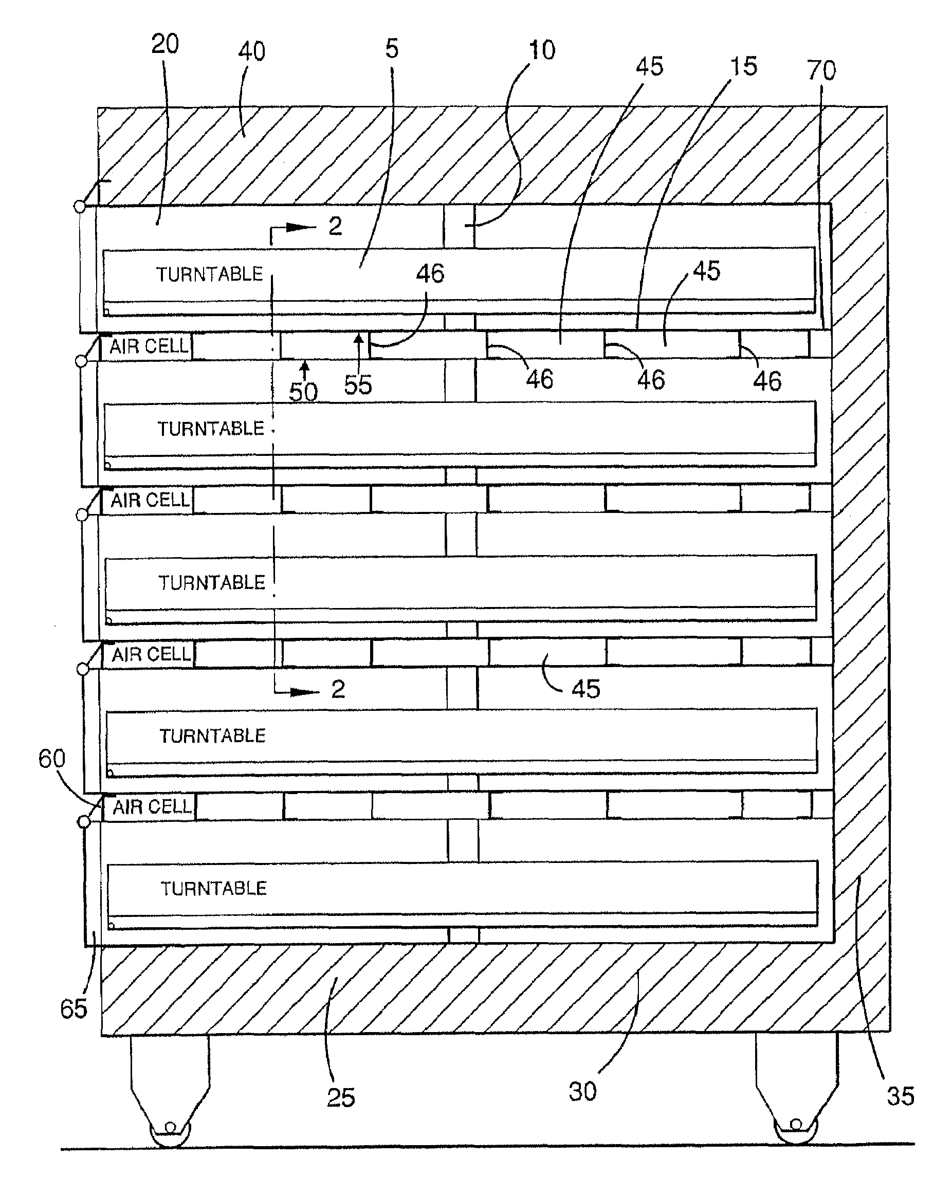
[0026]FIG. 1 illustrates a five deck baking oven, such as a Rotel™ type oven design, where each of the baking chambers 20 has a turntable 5 which revolve around a central shaft 10. Due to the rotating turntables, the heating elements (not shown), typically kelrod™ type electrically powered elements, are mounted above the oven (turntable) floor of each baking chamber. As the heating elements are not proximate to the insulation layer 15, relatively less insulation is required to retain the heat within each baking chamber 20.

[0027]The floor of the bottom most baking chamber 25 is typically fully sealed to the wall members of the internal oven housing cell 30. The roof of the top most baking chamber 40 is likewise sealed. Housing insulation under the bottom oven floor 30, oven side walls 36, and roof 40, retain heat in these housing members.

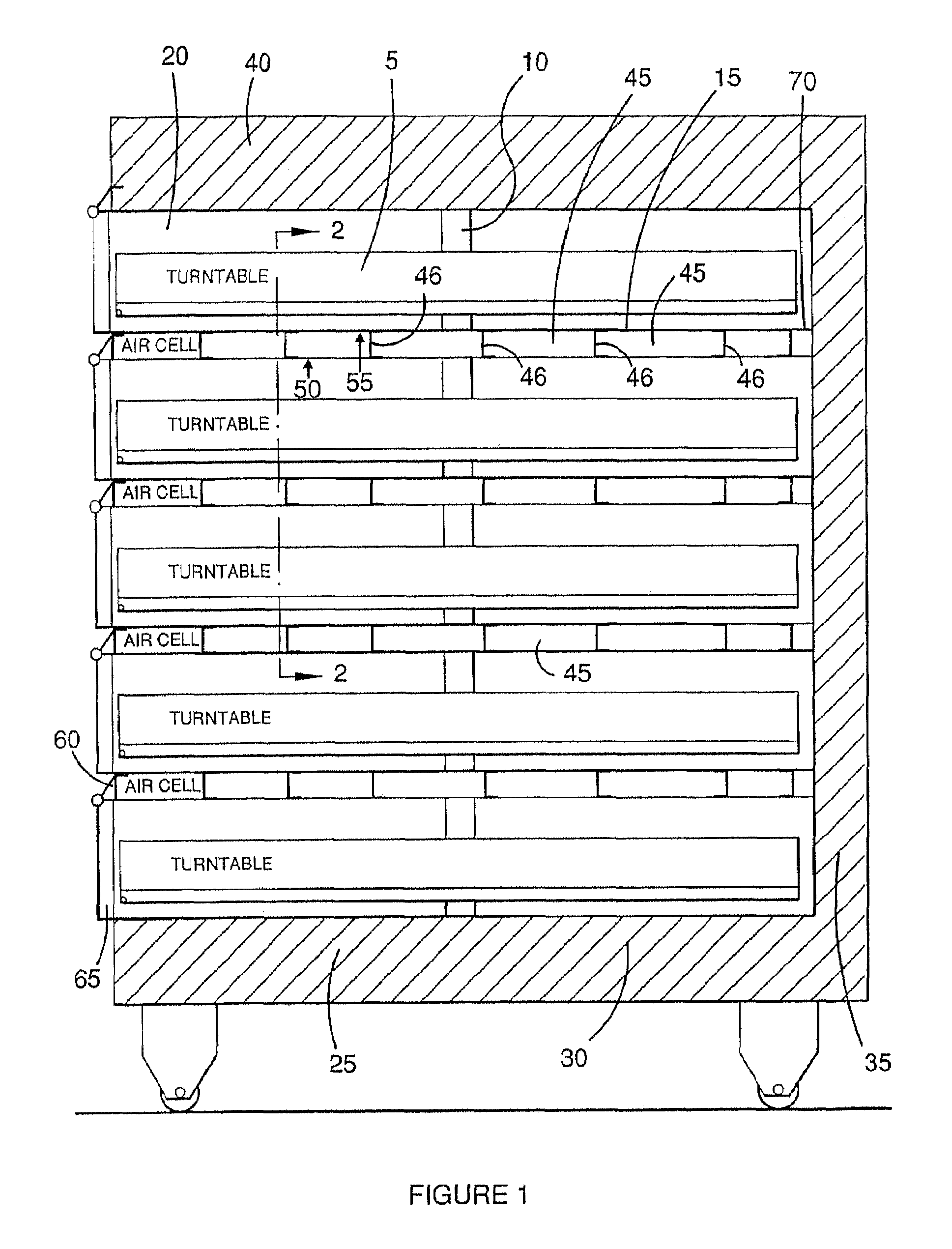
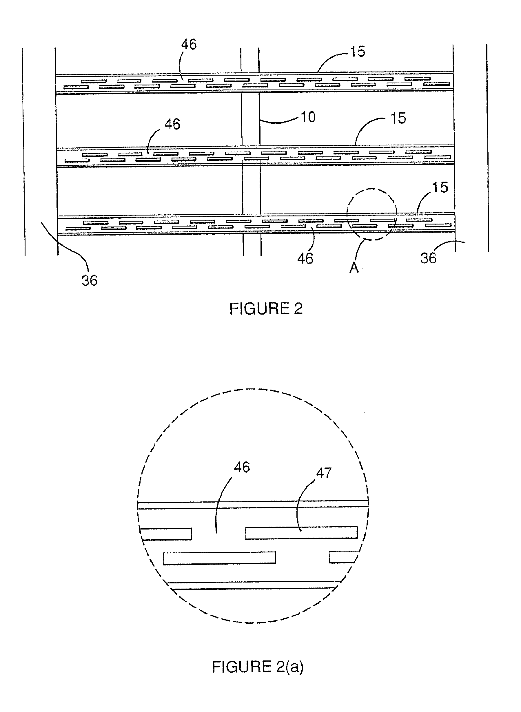
[0028]The insulation layer comprises a number of air cells or voids 45 separated by rib members or struts 46 which extend between oven side walls 36...


PUM


Abstract

A multi-deck baking oven including a housing and at least two baking chambers located within the housing, adjacent baking chambers being separated by an insulating layer, at least one of the insulating layers including a hollow partition, wherein each insulating layer dampens the rate of heat flow between the adjacent baking chambers.

Description

FIELD OF THE INVENTION[0001]The present invention relates to ovens for the baking of pastry products and, in particular, insulation for multi-deck type baking ovens.BACKGROUND OF THE INVENTION[0002]It is common for baking ovens to have a number of individual chambers or decks, mounted usually one above the other. This design permits several different products to be baked at once. In this arrangement, each product is located on a separate deck, having its own air temperature, steam atmosphere and bake time.[0003]Separating one baking chamber from another is usually accomplished by inserting insulation (e.g. rockwool) between the baking chamber's floor and roof. This avoids unwanted heat from one baking chamber, travelling through to the walls which separate the adjacent baking chambers. The heating chambers are generally fully sealed from one another so that steam and byproducts of the baking process cannot travel into the insulating material, or into the other baking chambers.[0004]...

Claims


Application Information

Patent Timeline
Patent Type & Authority Patents(United States)
IPC IPC(8): F24C15/16
CPCA21B1/22A21B1/44F24C15/34Y02P60/80
Inventor WILLETT, PAUL EATON
Owner MOFFAT
Why Eureka
Try Eureka