
Low risk deployment passenger airbag system using slim type passenger airbag module

a passenger airbag and low-risk technology, applied in the direction of pedestrian/occupant safety arrangement, vehicular safety arrangments, vehicle components, etc., can solve the problems of severe neck injury of the child,

Active Publication Date: 2010-03-30
S&T DAEWOO +1
View PDF31 Cites 3 Cited by
  • Summary
  • Abstract
  • Description
  • Claims
  • Application Information

AI Technical Summary

Benefits of technology

[0024]Another object of the present invention is to provide a low risk passenger airbag system in which at least one of the top airbag and the mid airbag, which are respectively mounted to the upper surface and the front surface of the instrument panel, comprises a slim type passenger airbag module having minimal height and / or length, such that it can meet the low risk deployment criteria for passenger airbags set by the National Highway Traffic Safety Administration (NHTSA).
[0025]In order to accomplish the above object, in a first aspect of a slim type passenger airbag module used in the low risk deployment passenger airbag system, a disk type inflator is used, unlike the conventional art, which uses a cylindrical inflator, and an upper end of the disk inflator is disposed in an airbag housing. Furthermore, a retainer for supporting the cushion is brought into close contact with the bottom of the airbag housing and integrally fastens the cushion and the disk type inflator to the airbag housing, thus reducing the height and / or length of the passenger airbag module.
[0026]In a second aspect of a slim type passenger airbag module used in the low risk deployment passenger airbag system, the opening in the airbag housing, through which the cushion is deployed, and the upper surface of the disk type inflator, which supplies deployment gas into the cushion, are perpendicular to each other, so that the height of the opening can be determined independent of the size of the disk type inflator, thus reducing the height or length of the passenger airbag module.

Problems solved by technology

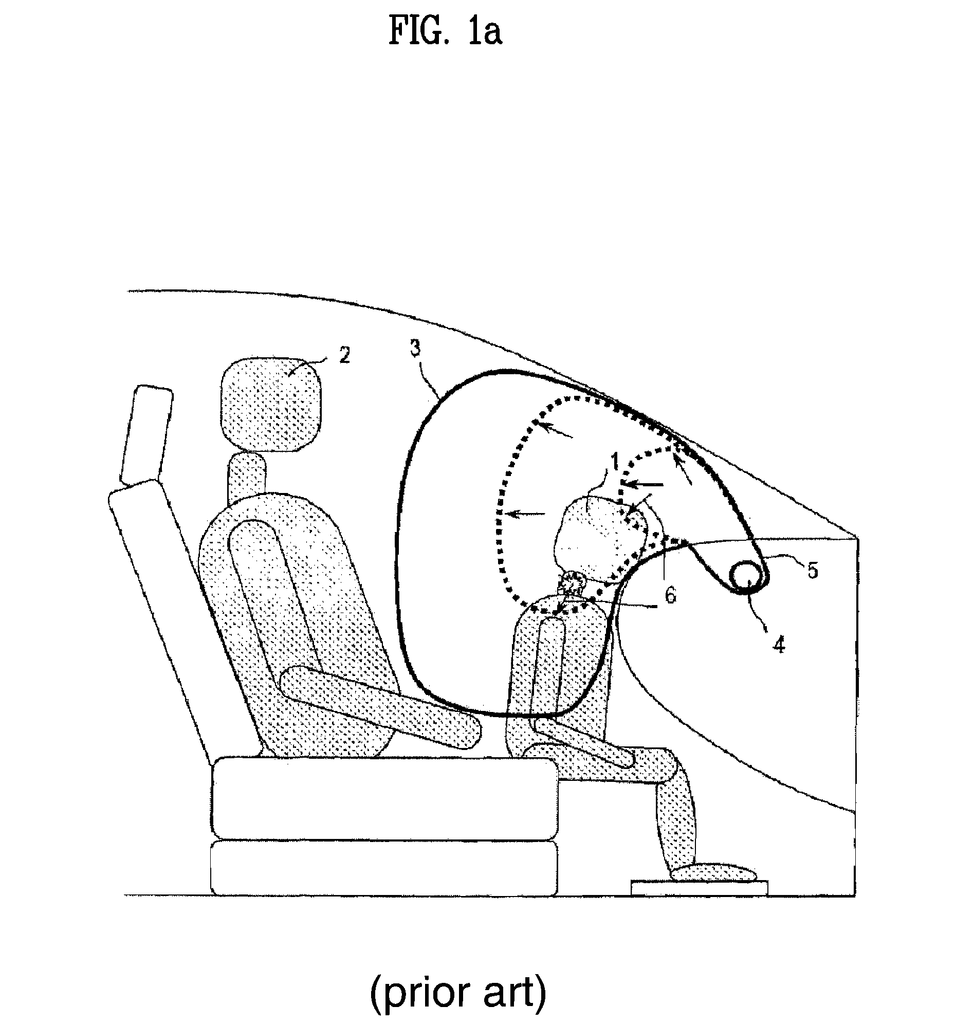
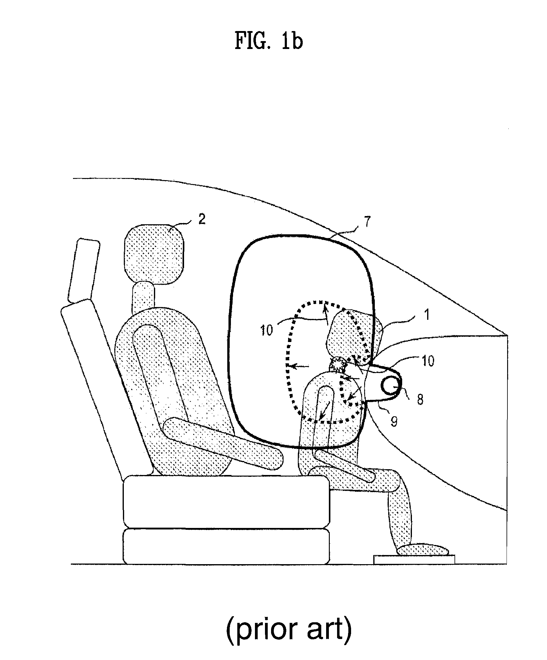
However, the conventional passenger airbag system having the single top or mid airbag is problematic in that, when a vehicle accident occurs, a cushion inflated towards a passenger seat strikes the head of an out-of-position occupant (OOP), such as a child or a small adult, thus resulting in a severe injury to his / her neck.
The downward deployment component force 6 strikes the head of a child 1, who is adjacent to the instrument panel, in a downward direction, thus resulting in a severe injury to the neck of the child 1.
The upward deployment component force 10 strikes the jaw of an out-of-position child 1 in an upward direction, thus resulting in a severe injury to the neck of the child.
Thus, when the airbag is deployed, that is, when the top airbag and the mid airbag are deployed, they are operated in conjunction with each other, so that they are substantially horizontally deployed towards the head and the chest of the occupant, thus preventing the downward or upward deployment component force 6 or 10 resulting in an injury to the neck of the out-of-position child.
That is, in such a low risk deployment passenger airbag system, because the top airbag module and the mid airbag module must be mounted to the rear surface of the instrument panel in a limited space defined by the instrument panel, the installation area and space are insufficient.
Furthermore, because a glove box (GB) must be installed inside the front panel of the instrument panel 65, the mid airbag module M cannot be installed in that area.

Method used


Image

  • Low risk deployment passenger airbag system using slim type passenger airbag module
  • Low risk deployment passenger airbag system using slim type passenger airbag module
  • Low risk deployment passenger airbag system using slim type passenger airbag module

Examples


first embodiment

[0044]FIGS. 5a, 5b and 5c are a perspective view, an exploded perspective view and a sectional view showing a slim type passenger airbag module 101 used in a low risk deployment passenger airbag system, according to the present invention.

[0045]As shown in the drawings, the slim type passenger airbag module 101 includes a box-shaped airbag housing 20, which has an opening 25 in an upper end thereof, and a disk type inflator 30, which is mounted to the bottom 23 of the airbag housing 20 and discharges deployment gas. The slim type passenger airbag module 101 further includes a cushion 40 to be inflated through the opening 25 towards a passenger seat by deployment gas discharged from the disk type inflator 30, and a retainer 50, which fastens an inlet part 41 (see, FIG. 5b) of the cushion 40 and the disk type inflator 30 to the bottom 23 of the airbag housing 20.

[0046]In detail, the box-shaped airbag housing 20 is made of plastic or metal and has in the upper end thereof the opening 25...

second embodiment

[0052]Next, a slim type passenger airbag module 102 used in a low risk deployment passenger airbag system according to the present invention will be described herein below with reference to the attached drawings.

[0053]FIGS. 6a and 6b are a perspective view and a sectional view showing the slim type passenger airbag module 102 used in the low risk deployment passenger airbag system, according to the second embodiment of the present invention. As shown in the drawings, the slim type passenger airbag module 102 according to the second embodiment of the present invention includes a box-shaped airbag housing 20, which has an opening 25 in a front end thereof, and a disk type inflator 30, which is mounted to the bottom 23 of the airbag housing 20 and discharges deployment gas. The slim type passenger airbag module 102 further includes a cushion 40 which is inflated through the opening 25 towards a passenger seat by deployment gas discharged from the disk type inflator 30, and a retainer 5...

third embodiment

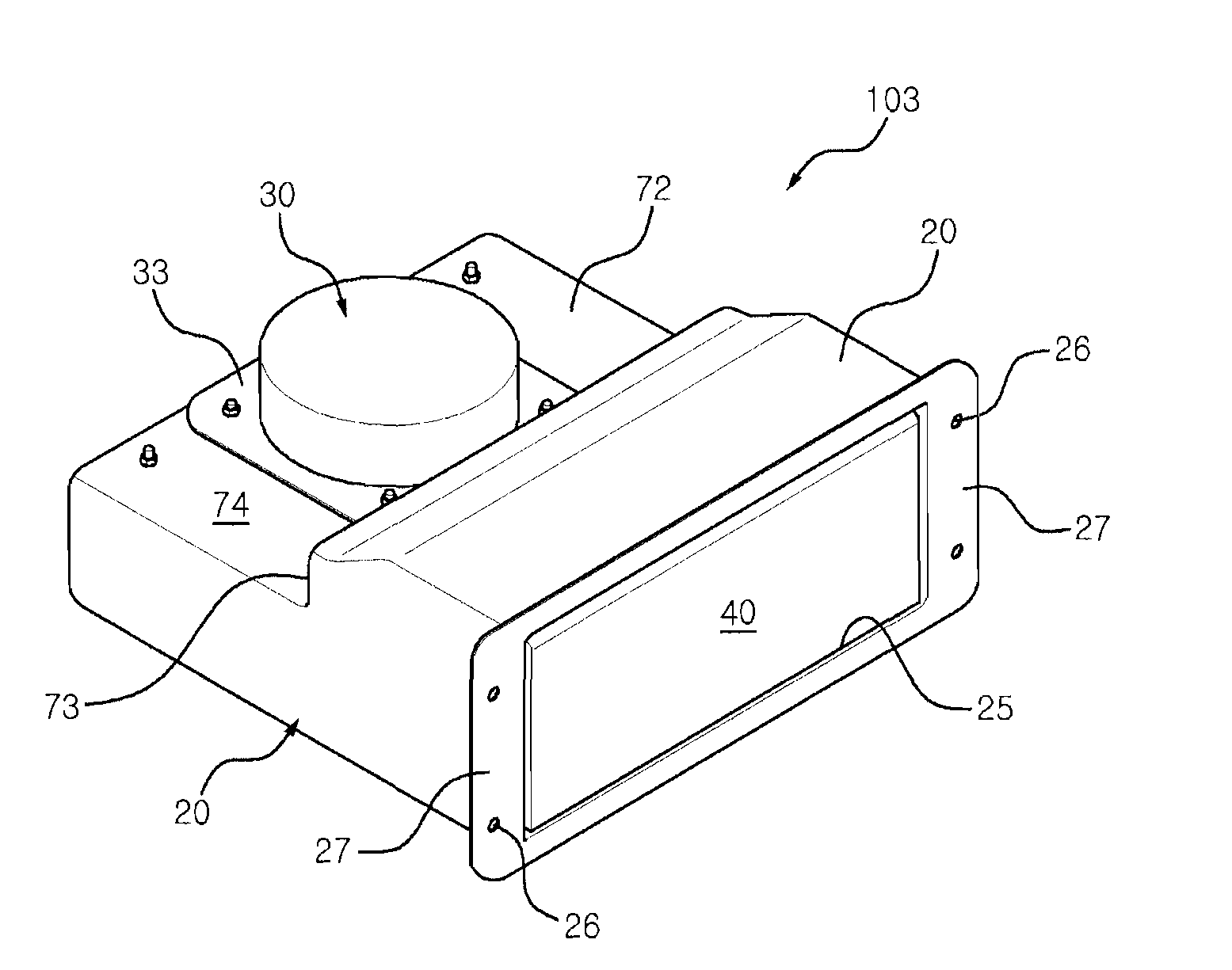
[0061]In detail, the slim type passenger airbag module 103 includes the box-shaped airbag housing 20, which has an opening 25 in a front end thereof and has the stepped part 73 at an intermediate position thereof so that the cushion receiving part 71, in which the cushion 40 is placed, is higher than the other part of the airbag housing 20. The slim type passenger airbag module 103 further includes the disk type inflator 30, which is mounted to the upper surface 23 of the inflator receiving part 74 of the airbag housing 20 and discharges deployment gas, the cushion 40 to be inflated through the opening 25 towards a passenger seat by deployment gas discharged from the disk type inflator 30, and the retainer 50, which fastens the inlet part 41 (see, FIG. 7b) of the cushion 40 and a ring-shaped flange 33 of the disk type inflator 30 to the upper surface 74 of the inflator receiving part 72 of the airbag housing 20. The general construction of the slim type passenger airbag module 103,...


PUM


Abstract

Disclosed herein is a low risk deployment passenger airbag system using a slim type passenger airbag module which is minimized in height and / or length, such that a top airbag and a mid airbag can be installed in a limited space defined by an instrument panel. In the slim type passenger airbag module used in the low risk deployment passenger airbag system, a disk type inflator is used, unlike the conventional art using a cylindrical inflator, an upper end of the disk inflator is disposed in an airbag housing, and a retainer for supporting the cushion is brought into close contact with the bottom (or the rear surface) of the airbag housing in which the disk type inflator is provided, thus minimizing the height and / or length of the passenger airbag module. Thereby, the slim type passenger airbag module is suitable for the low risk deployment passenger airbag system. Furthermore, in the low risk deployment passenger airbag system, to deploy the cushions of the top and mid airbags substantially horizontally towards a passenger seat when a vehicle accident occurs, the distance between the top airbag and the mid airbag is within a range from 100 mm to 250 mm, the top airbag is inclined at an angle ranging from 60° to 75° with respect to the horizontal surface, and the mid airbag is inclined at 15° or less with respect to the horizontal surface.

Description

CROSS REFERENCE TO RELATED APPLICATIONS[0001]This application is a division of U.S. patent application Ser. No. 11 / 657,327, filed Jan. 24, 2007, which is incorporated by reference as if fully set forth.BACKGROUND OF THE INVENTION[0002]1. Field of Invention[0003]The present invention relates generally to passenger airbag modules mounted to instrument panels of vehicles and low risk deployment passenger airbag systems having top airbags and mid airbags which are respectively mounted to upper surfaces and front surfaces of instrument panels and, more particularly, to a low risk deployment passenger airbag system using a slim type passenger airbag module which is minimized in height and / or length, such that two passenger airbag modules, that is, a top airbag and a mid airbag, can be installed in a limited space defined by an instrument panel.[0004]2. Description of the Related Art[0005]Generally, airbag modules are installed in vehicles to protect drivers and passengers from major impac...

Claims


Application Information

Patent Timeline
Patent Type & Authority Patents(United States)
IPC IPC(8): B60R21/205B60R21/217B60R21/231
CPCB60R21/205B60R21/237B60R2021/23107B60R21/20B60R21/16
Inventor KIM, DONG EUNPARK, YOUNG YEOLNAM, JONG SEOPSONG, SEUNG JAE
Owner S&T DAEWOO
Learn More