Acoustic fluid flow device for printing system

a printing system and fluid flow technology, applied in printing and other directions, can solve the problems of reducing drop placement accuracy, and affecting accuracy of drop deflection or divergen

Inactive Publication Date: 2010-03-30
EASTMAN KODAK CO
View PDF10 Cites 4 Cited by
  • Summary
  • Abstract
  • Description
  • Claims
  • Application Information

AI Technical Summary

Problems solved by technology

The device that provides gas flow to the gas flow drop interaction area can introduce turbulence in the gas flow that may augment and ultimately interfere with accurate drop deflection or divergence.
For example, when relatively small volume drops are caused to deflect or diverge from the path by the gas flow force, turbulence can randomly disorient small volume drops resulting in reduced drop deflection or divergence accuracy which, in turn, can lead to reduced drop placement accuracy.

Method used


Image

  • Acoustic fluid flow device for printing system
  • Acoustic fluid flow device for printing system
  • Acoustic fluid flow device for printing system

Examples


Embodiment Construction

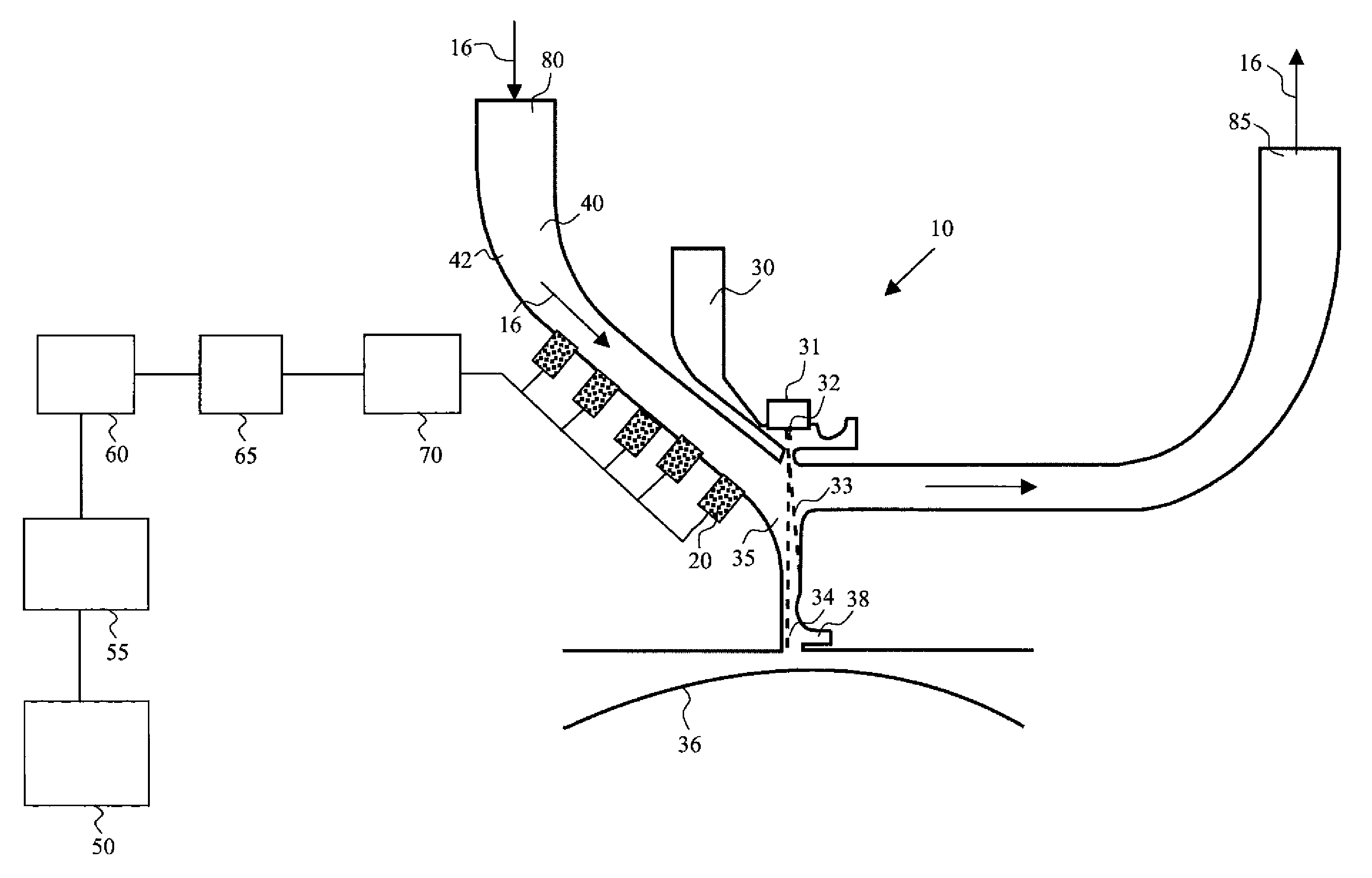
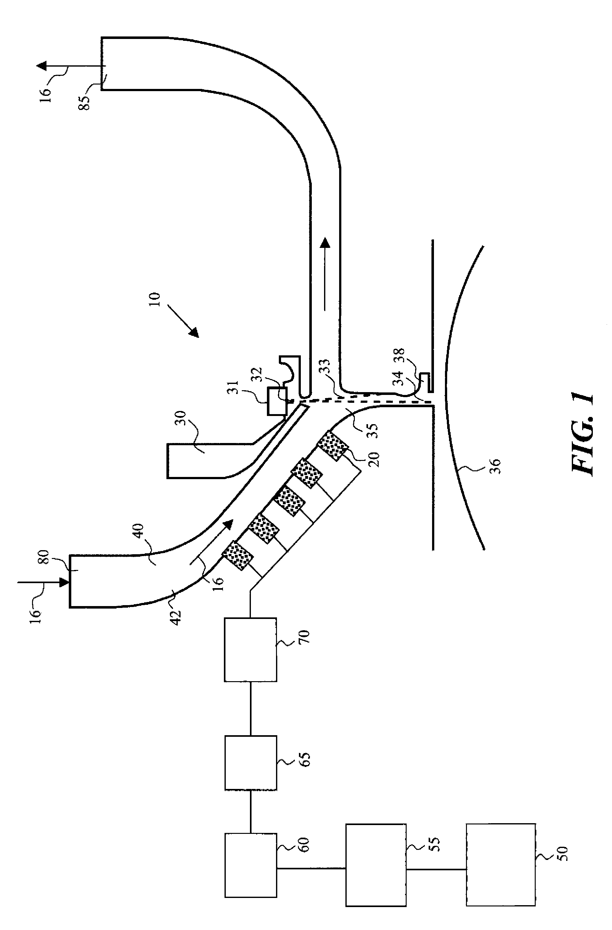
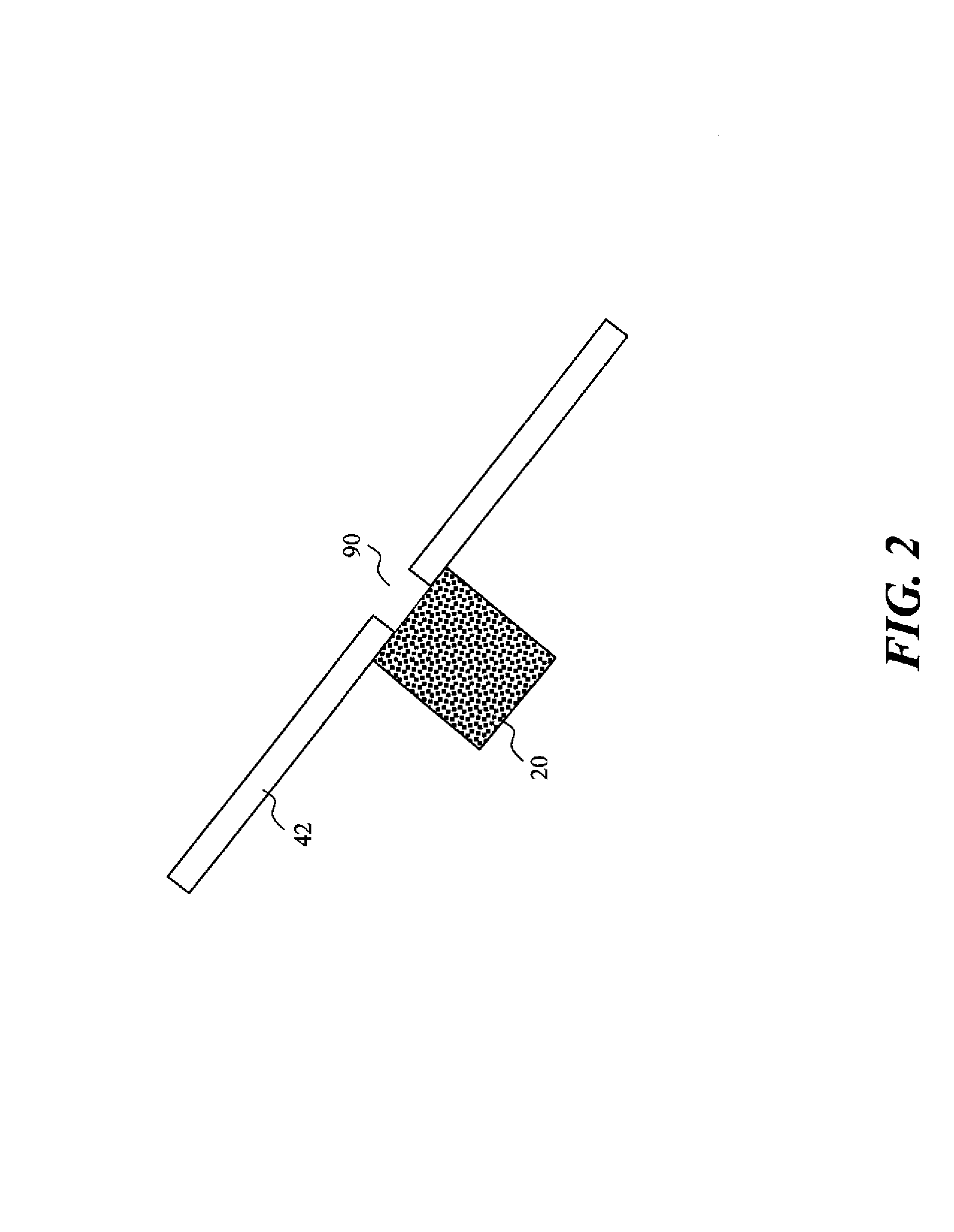
[0015]The present description will be directed in particular to elements forming part of, or cooperating more directly with, apparatus in accordance with the present invention. It is to be understood that elements not specifically shown or described may take various forms well known to those skilled in the art.

[0016]The example embodiments of the present invention are illustrated schematically and not to scale for the sake of clarity. One of ordinary skill in the art will be able to readily determine the specific size and interconnections of the elements of the example embodiments of the present invention. In the following description, identical reference numerals have been used, where possible, to designate identical elements.

[0017]Although the term printing system is used herein, it is recognized that printing systems are being used today to eject other types of liquids and not just ink. For example, the ejection of various fluids such as medicines, inks, pigments, dyes, and other...


PUM


Abstract

A printing system includes a liquid drop ejector, a fluid passage, and a fluid flow source. The liquid drop ejector is operable to form liquid drops having a plurality of volumes moving along a first path. The fluid passage includes a wall. A source of acoustic energy is associated with the wall. A fluid flow source is associated with the passage and is configured to provide a fluid flow through the passage. Interaction of the fluid flow and the liquid drops causes liquids drops having one of the plurality of volumes to begin moving along a second path.

Description

CROSS REFERENCE TO RELATED APPLICATIONS[0001]Reference is made to commonly-assigned, U.S. patent application Ser. No. 11 / 770,774, filed currently herewith, entitled “ENERGY DAMPING FLOW DEVICE FOR PRINTING SYSTEM,” and U.S. patent application Ser. No. 11 / 770,804, filed currently herewith, entitled “PERFORATED FLUID FLOW DEVICE FOR PRINTING SYSTEM.”FIELD OF THE INVENTION[0002]This invention relates generally to the management of fluid flow and, in particular to the management of fluid flow in printing systems.BACKGROUND OF THE INVENTION[0003]Printing systems that deflect drops using a gas flow are known, see, for example, U.S. Pat. No. 4,068,241, issued to Yamada, on Jan. 10, 1978.[0004]The device that provides gas flow to the gas flow drop interaction area can introduce turbulence in the gas flow that may augment and ultimately interfere with accurate drop deflection or divergence. Turbulent flow introduced from the gas supply typically increases or grows as the gas flow moves throu...

Claims


Application Information

Patent Timeline
Patent Type & Authority Patents(United States)
IPC IPC(8): B41J2/09B41J2/105
CPCB41J2/02B41J2/175B41J2002/031B41J2002/033
Inventor GAO, ZHANJUNXU, JINQUAN
Owner EASTMAN KODAK CO
Why Eureka
Try Eureka