Photoacoustic Sensor

a technology of photoacoustic waves and sensors, applied in the field of photoacoustic sensors, can solve the problems of compromising the sensitivity of the transducer for detecting photoacoustic waves and determining their origins, and generally affecting the sensitivity of at least one transducer, so as to reduce aiming constraints, reduce sensitivity, and reduce the effect of output apertur

Inactive Publication Date: 2007-09-06
GLUCON
View PDF14 Cites 159 Cited by
  • Summary
  • Abstract
  • Description
  • Claims
  • Application Information

AI Technical Summary

Benefits of technology

[0011] In accordance with an embodiment of the invention, a photoacoustic sensor comprises a light provider having an optical output aperture formed in a planar light pipe and at least one acoustic transducer. The photoacoustic sensor's at least one acoustic transducer is coupled to the planar light pipe so that acoustic energy incident on the optical output aperture is sensed by the at least one acoustic transducer. The photoacoustic sensor as a result is not “blind” to acoustic energy incident on the optical output aperture and sensitivity of the photoacoustic sensor is therefore substantially unaffected by size of

Problems solved by technology

The blind spot generally adversely affects sensitivity of the at least one transducer for detecting photoacoustic waves generated in the region and for determining coordinates of the origins of the photoacoustic waves.
However, for a light provider having a small output aperture it can be relatively difficult to aim light from the light provider so that it properly and over

Method used


Image

  • Photoacoustic Sensor
  • Photoacoustic Sensor
  • Photoacoustic Sensor

Examples


Embodiment Construction

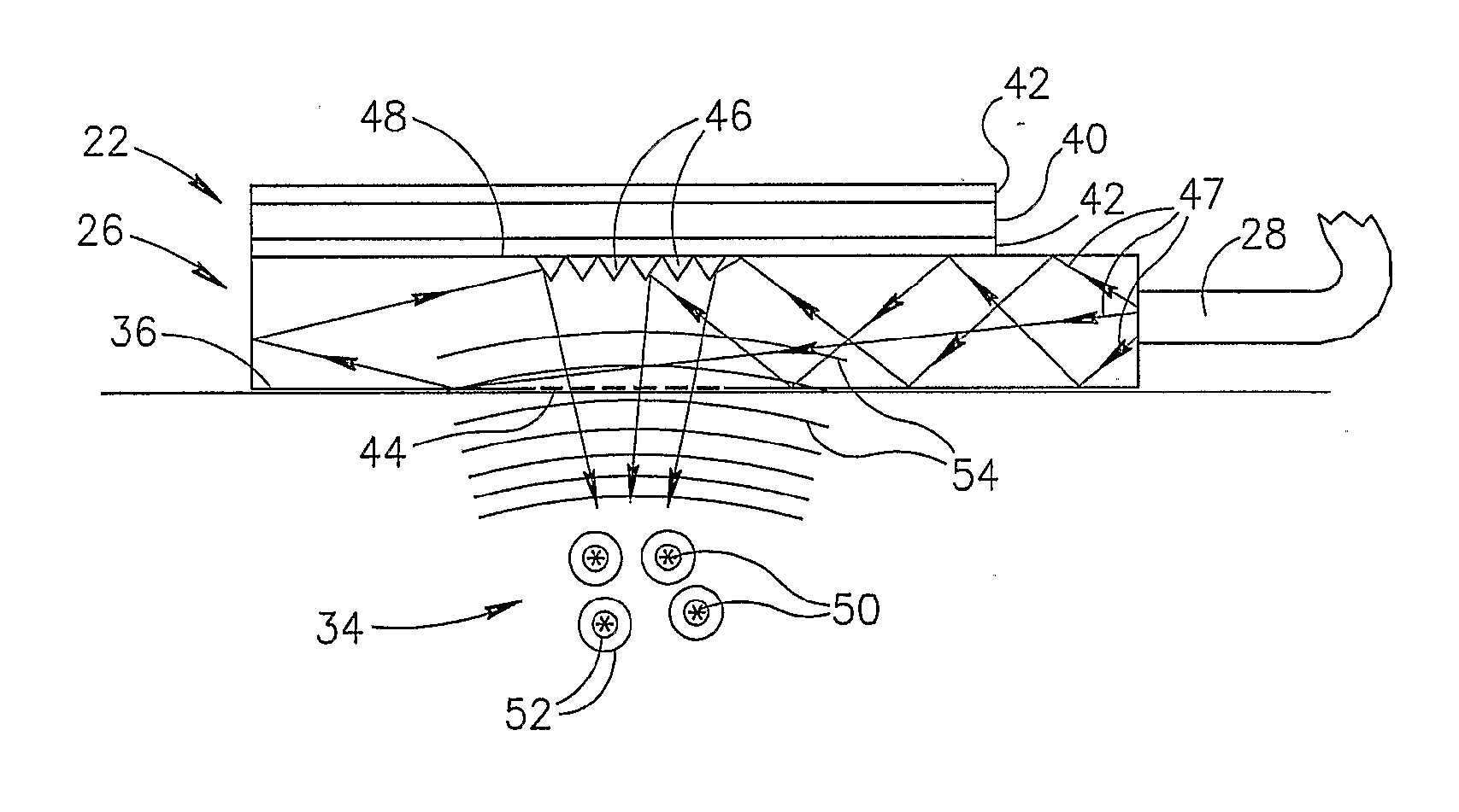
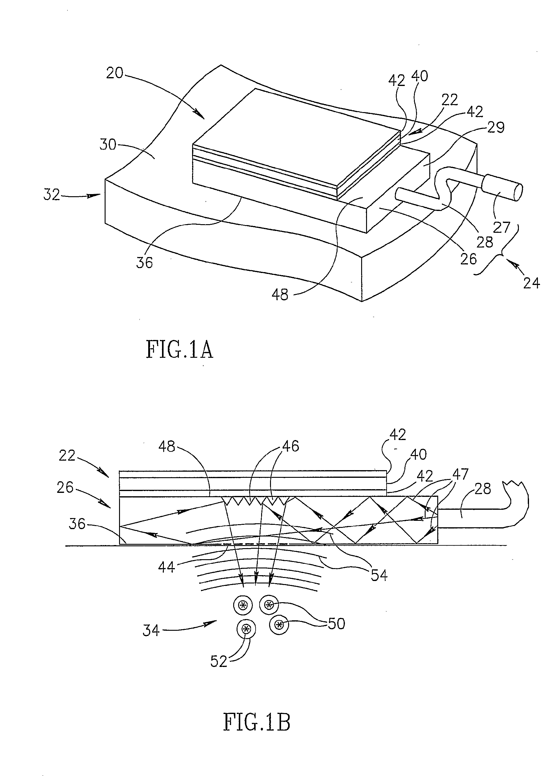
[0036]FIGS. 1A and 1B schematically show a perspective view and a cross-section view respectively of a photoacoustic sensor 20, in accordance with an embodiment of the present invention.

[0037] Photoacoustic sensor 20 comprises, at least one, optionally planar, acoustic transducer 22 and a light provider 24. Light provider 24 comprises a planar light pipe 26 and optionally an optic fiber 28 coupled to a light source 27 and to the light pipe along an edge surface 29 of the light pipe. Planar light pipe 26 is bonded to at least one transducer 22, which by way of example comprises a single transducer. Photoacoustic sensor 20 is schematically shown coupled to a surface 30 of body 32 so as to generate and sense photoacoustic waves in a region 34 (shown in FIG. 1B) of the body. Coupling of the photoacoustic sensor to surface 30 is achieved by coupling a bottom surface 36 of light pipe 26 to surface 30. Optionally, coupling of the light pipe to surface 30 is aided by use of a suitable gel ...


PUM


Abstract

Apparatus for stimulating photoacoustic waves in a region of a body and generating signals responsive to the stimulated waves comprising: a light source (27) that provides light that stimulates photoacoustic waves (54) in the region; a light pipe (26) having an output aperture (80) and at least one input aperture, which light pipe receives the light from the light source at the at least one input aperture and transmits the received light to illuminate the region from the output aperture; and at least one acoustic transducer (22) that generates signals responsive to acoustic energy from the photoacoustic waves that is incident on the optical output aperture.

Description

RELATED APPLICATIONS [0001] The present application claims the benefit under 35 USC 119(e) of U.S. provisional application 60 / 535,832 filed on Jan. 13, 2004, the disclosure of which is incorporated herein by reference.FIELD OF THE INVENTION [0002] The invention relates to apparatus for stimulating and sensing photoacoustic waves in a medium. BACKGROUND OF THE INVENTION [0003] In a photoacoustic effect, light that illuminates a body is absorbed by a region of the body and a portion of the absorbed optical energy is converted to acoustic energy that propagates away from the absorbing region as acoustic, i.e. “photoacoustic”, waves. The photoacoustic effect is typically used for imaging internal features of a body and / or assaying analytes in the body. [0004] Devices, hereinafter “photoacoustic sensors”, that use the photoacoustic effect to determine a characteristic of a region of a body, generally comprise at least one acoustic transducer and a light provider having an output aperture...

Claims


Application Information

Patent Timeline
IPC IPC(8): G01N21/00A61B5/00G01N21/17
CPCA61B5/0059G01N21/1702A61B5/14546A61B5/0095
Inventor PESACH, BENNY
Owner GLUCON
Why Eureka
Try Eureka