
Method and circuitry for charging a capacitor to provide a high pulsed power discharge

Inactive Publication Date: 2006-04-06
NOVACENTRIX INC
View PDF2 Cites 38 Cited by
  • Summary
  • Abstract
  • Description
  • Claims
  • Application Information

AI Technical Summary

Benefits of technology

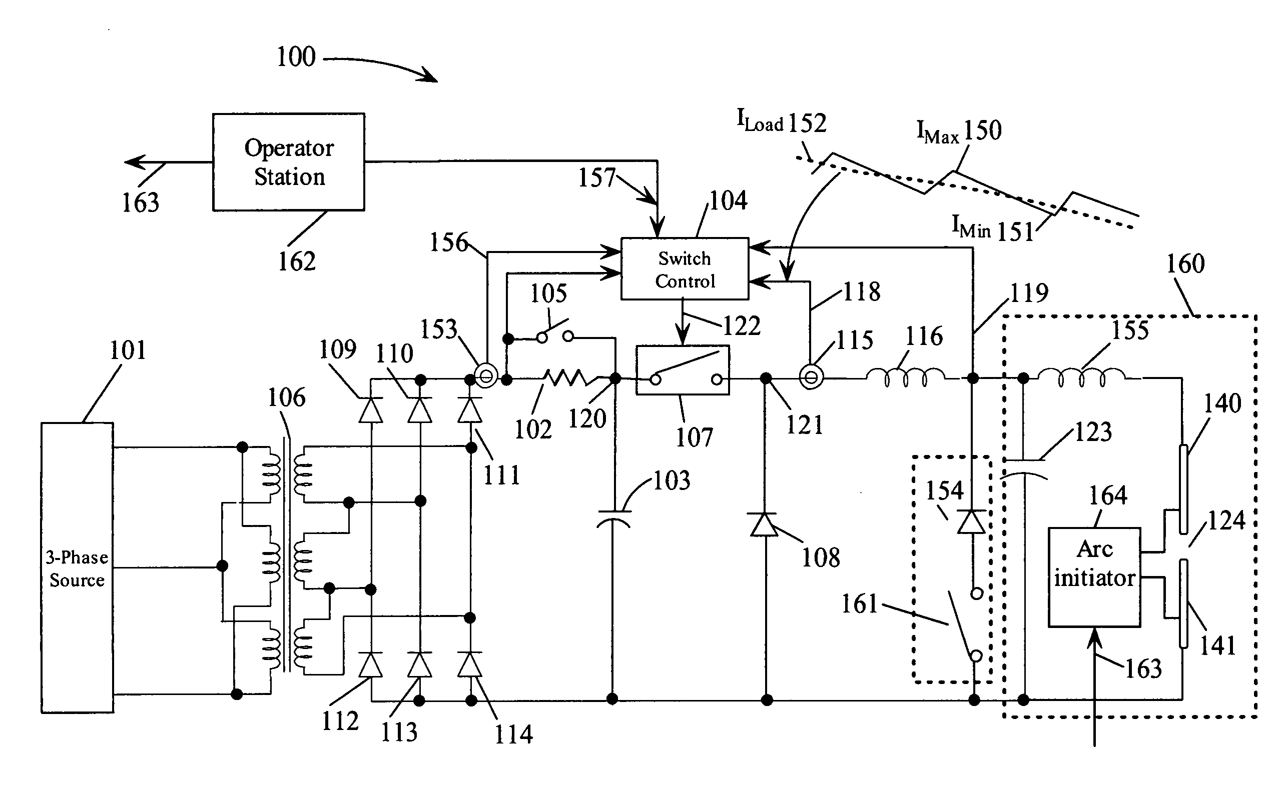
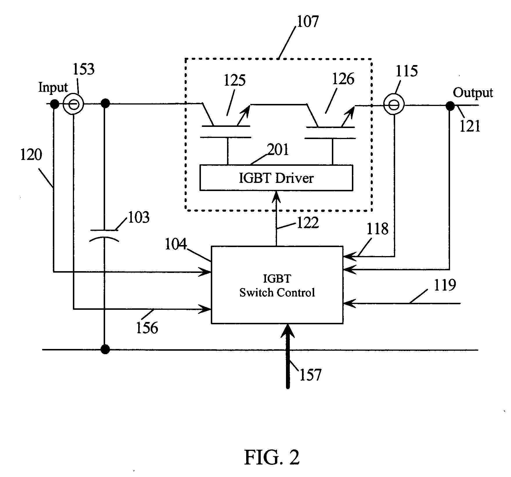
[0010] The instantaneous current through the current regulating inductor is sensed and used to regulate the capacitor charging current between a lower level and an upper level by turning the electronic switch ON when the output current drops below the lower current level and by turning the electronic switch OFF when the output current increases above the upper current level. Since the DC high voltage is unregulated and the current is regulated using the same components needed for fast response short-circuit protection, the power system is very economical. The switching frequency for the electronic switch is determined by the time period to increase the current from the lower level to the upper level and to decrease from the upper level to the lower level. In this sense the switching frequency is “free running” without a fixed forced value.
[0012] The current control mode selected for a particular application depends on the requirements for the application. Constant current mode minimizes the power dissipation in the power supply components averaged over a charging cycle and hence delivers the maximum average power output for a given power supply implementation. A constant RMS input power mode minimizes strain on the local AC power distribution system. This mode may be required for very high power systems or when operation in environments where large fluctuations in the local AC power voltage and load cannot be tolerated. A constant output power mode provides nearly the same benefits as the constant RMS input power mode, however the constant output power mode responds faster to changing load conditions.
[0014] Since the charging current is rapidly controlled and has a predetermined maximum value, the regulating circuitry does not have to be turned OFF during a discharge cycle. If a non-clearing short circuit condition is sensed on the output, the fast electronic switch may be switched OFF. Any energy stored in the current regulating inductor continues to charge the capacitor bank through a free-wheeling diode coupled between ground and the output of the electronic switch. Action to disable current control may be taken if it is determined that a short circuit is sustained. The power system of the present invention can continue to supply controlled current to the capacitor bank even during a rapid discharge. If the charging current is not sufficient in itself to sustain an arc, as soon as the arc extinguishes, charging will immediately resume allowing for faster operation with less dead time. The electronic switch may also be turned OFF if the voltage across the capacitor bank exceeds a predetermined maximum level. Hysterisis may be employed to control when switching action is again enabled after a maximum output voltage level has been reached and the bank voltage subsequently drops due to a non-zero load impedance.
[0015] The power system of the present invention tolerates frequent and unexpected virtual short circuit conditions, rapidly recovers from short circuit conditions, and does not need to be turned OFF during normal operations when a virtual short circuit is initiated across the capacitor bank during high pulsed power discharges. These attributes result in the highest possible output duty cycle. Since the power system of the present invention uses no resistive limiting elements during normal operation, it provides high power efficiency. The power system also tolerates ringing capacitor discharges and tolerates accidental disconnections of the capacitor bank without damage. The present invention, therefore, provides a highly reliable and economical power system for charging a capacitor bank that is suitable for demanding manufacturing or industrial applications.

Problems solved by technology

This design has very poor power efficiency and is unacceptable for high power applications where currents may range up to 1000 amperes and voltages may range up to 20,000 volts.
This timescale may be too long for high power applications as the surge current that occurs while waiting for SCR turn OFF can still damage components in the power supply section.
However, such high power electronic switches may still switch too slowly to prevent the SCRs from being damaged during an unanticipated output short circuit.
Adding the series inductor creates additional problems of voltage spikes which may in turn damage the electronic switch if not controlled.
Prior art high voltage charging systems typically have severe limitations with regard to conditions for charging and discharging the capacitor bank.
In particular, prior art charging systems typically use low power output diodes which are directly in the pulsed discharge current path if the capacitor voltage swings to the opposite polarity (rings).
Depending on implementation details, this type of circuit, without additional protection circuitry, is not able to tolerate discharging the capacitor bank during charging, ringing capacitor discharges, or accidental disconnection from a capacitive load.
Without protection, this type of supply is not robust.
Prior art high power charging systems suffer from one or more serious shortcomings including low power efficiency with or without external short-circuit protection (which also adds complexity), significant notching of the input AC power, high cost, inability to tolerate a ringing capacitor discharge, or destruction of the supply if accidentally disconnected from the capacitive load while charging.
They also typically cannot operate in a continuous charging mode because they fail to recover rapidly from short-circuit conditions and / or it is necessary to disconnect the supply from the capacitor bank before a pulsed power discharge.
If the capacitor bank is used as part of a high pulsed power manufacturing process, these shortcomings significantly increase system cost, reduce reliability, and severely limit production rates.

Method used


Image

  • Method and circuitry for charging a capacitor to provide a high pulsed power discharge
  • Method and circuitry for charging a capacitor to provide a high pulsed power discharge
  • Method and circuitry for charging a capacitor to provide a high pulsed power discharge

Examples


Embodiment Construction

[0027] In the following description, numerous specific details are set forth to provide a thorough understanding of the present invention. However, it will be obvious to those skilled in the art that the present invention may be practiced without such specific details. In other instances, well-known circuits may be shown in block diagram form in order not to obscure the present invention in unnecessary detail. For the most part, details concerning timing, and the like have been omitted inasmuch as such details are not necessary to obtain a complete understanding of the present invention and are within the skills of persons of ordinary skill in the relevant art.

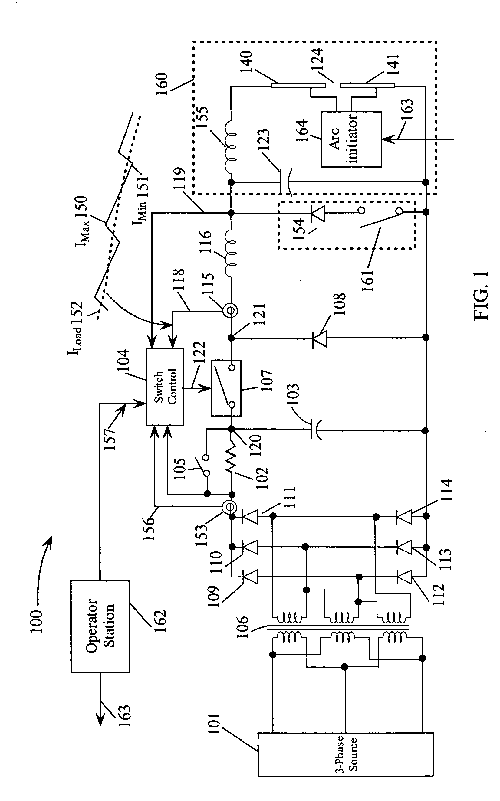
[0028]FIG. 1 is a circuit diagram of a capacitor bank charging power system 100 for an arc discharging process 160 according to embodiments of the present invention. Three phase 50 / 60 Hz power source 101 is coupled to the primary of a 3-phase isolation transformer 106. While it is most common to have 50 / 60 Hz AC line voltage ...


PUM


Abstract

An AC power source is coupled to a step-up transformer that provides a rectified DC output voltage to charge an intermediate capacitor. A high voltage electronic switch is turned ON and OFF by a control signal to couple and decouple the intermediate capacitor to the input of an inductor that supplies current to a capacitor bank. A switching regulator controller generates a control signal to vary the turn ON and OFF times of the electronic switch to generate a controlled current through the inductor while the voltage across the capacitor bank varies over a positive and negative voltage range during charging and discharging of the capacitor bank. The controlled current through the inductor is maintained while the capacitor bank is discharged. The value of the controlled current may be constant or varied in response to input and output voltage and current parameters.

Description

TECHNICAL FIELD [0001] The present invention relates in general to high voltage and high power capacitive charging supplies with circuitry that provides short circuit protection and withstands ringing capacitive loading. BACKGROUND INFORMATION [0002] To provide a high voltage, high current charging system for pulsed power applications usually entails charging a capacitor with a high voltage power supply over a relatively long time period and discharging the capacitor over a much shorter time period. The simplest circuit would entail a high constant voltage power supply with a current limiting resistor in series with the output. If a short circuit occurred across this power supply, additional circuitry would be needed to quickly disable the charging path or the current limiting resistor would have to be capable of dissipating power generated by the short circuit current until the output of the high voltage power supply is disabled. This design has very poor power efficiency and is un...

Claims


Application Information

Patent Timeline
IPC IPC(8): H02J7/00
CPCH02J7/0063H02J7/022H02J7/02H02J2207/20H02J7/00714H02J7/007182
Inventor ROSS, RENSSCHMIDT, STEPHEN JAMES
Owner NOVACENTRIX INC
Learn More