
Waveform shaping device and wave receiver

Active Publication Date: 2020-06-11
GREENERWAVE +2
View PDF1 Cites 1 Cited by
  • Summary
  • Abstract
  • Description
  • Claims
  • Application Information

AI Technical Summary

Benefits of technology

The patent describes a device that can improve the reception of a primary wave by a receiver. The device operates faster and more efficiently, meaning that optimal parameters lead to a better improvement of the reception of the primary wave by the receiver. This results in a better overall performance of the device. Additionally, the device consumes less internal energy and receives more via the primary wave, which is beneficial for autonomous devices. The processing also includes a technique called heterodyne detection, which lowers the frequencies of the measurement of the secondary wave.

Problems solved by technology

This shaping device therefore has a wireless connection with the mobile electronic device, which is sometimes impractical or very restrictive, particularly for the mobile electronic device which must manage two wireless communications: the wireless communication with the network and the wireless communication with the shaping device.
This periodicity is sometimes insufficient for a sufficiently rapid adaptation of the electromagnetic surface.

Method used


Image

  • Waveform shaping device and wave receiver
  • Waveform shaping device and wave receiver
  • Waveform shaping device and wave receiver

Examples


first embodiment

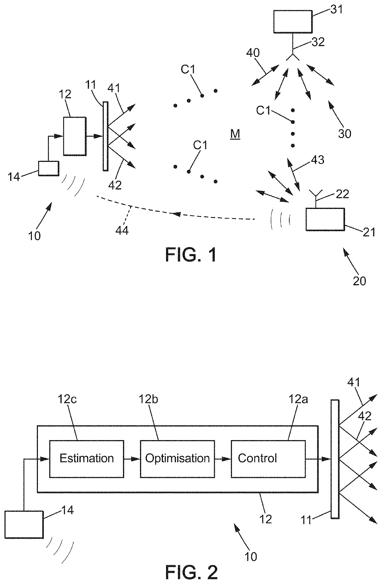
[0069]FIG. 1 shows a schematic view showing a general use of a wave shaping device 10 according to the invention, which improves the reception of a primary wave by a receiver 20.

[0070]The system as a whole comprises:[0071]a first device called a transmitter 30, adapted to at least emit a primary wave 40 in a wave propagation medium M, and possibly reciprocally receive a primary wave in this medium,[0072]a second device called the receiver 20, adapted to at least receive a transmitted primary wave 43 in this medium, said transmitted primary wave being transmitted directly or by reflections and / or transmissions, and / or a multiple combination of said transmissions and / or reflections, and[0073]a wave shaping device 10 adapted to improve, at the receiver 20, the reception of the primary wave 40 emitted by the transmitter 30 and received as a transmitted primary wave 43.

[0074]The transmitter 30 is a wireless emission device which comprises:[0075]an antenna array 32 which emits the primary...

second embodiment

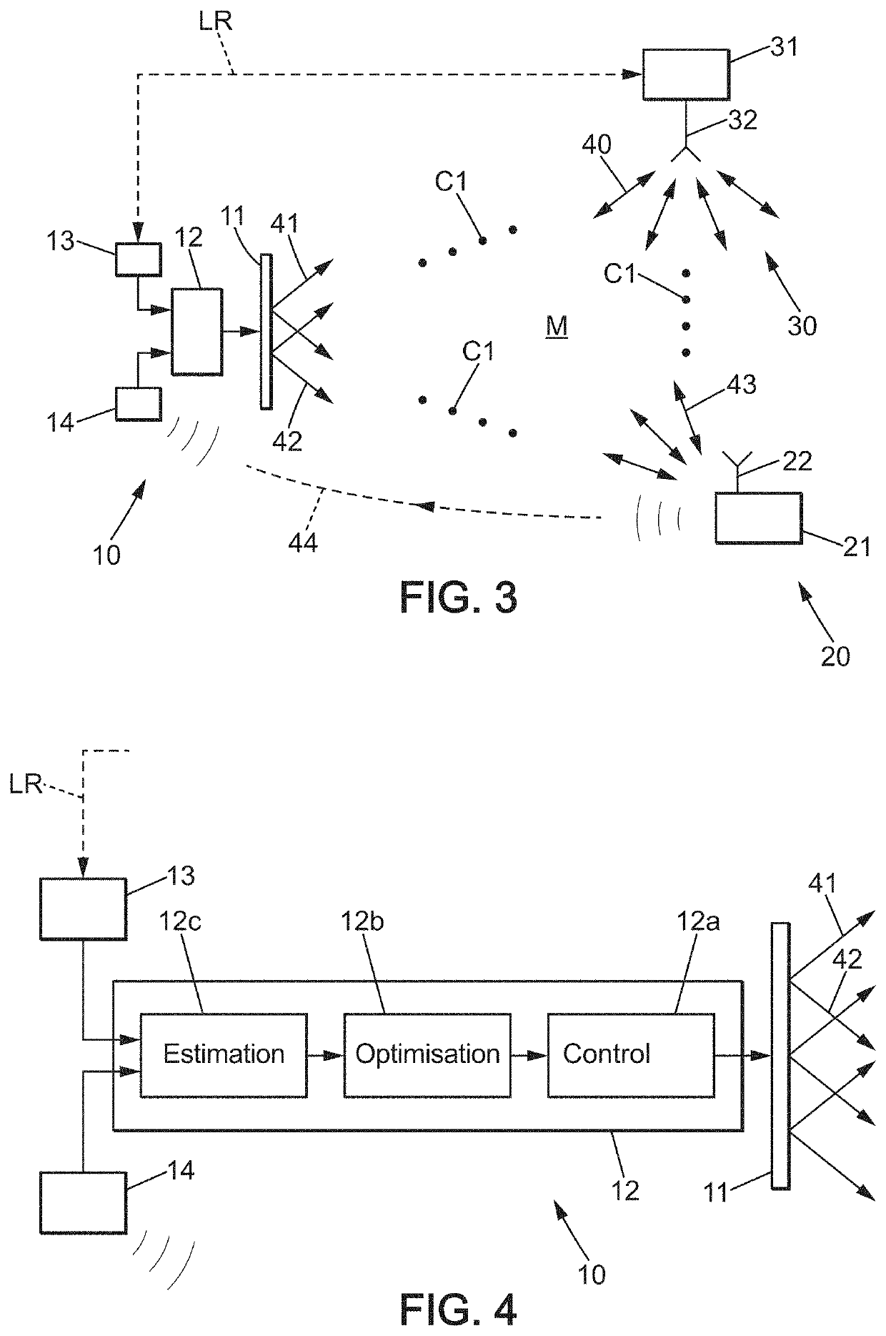
[0140]FIG. 3 shows a schematic view showing a general use of a wave shaping device 10 according to the invention, which improves the reception of a primary wave by a receiver 20.

[0141]The system of this second embodiment is similar to that of the first embodiment, and its variants can also be applied with the same respective advantages.

[0142]This embodiment differs from the previous one in that the shaping device 10 further comprises a transmission device 13 connected to the controller 12, and it is connected to the transmitter 30 (which emits the primary wave 40) by a network link LR in order to know the time instant at which the transmitter 30 emits the primary wave 40.

[0143]Furthermore, as represented in FIGS. 3 and 4, the estimation module 12c uses the measurement of the secondary wave and this time instant to extract the temporal portion of the measurement of the secondary wave 44 which is relevant for determining the estimated value concerning the reception by the receiver 20....


PUM


Abstract

Waveform shaping device including an adaptable surface, a controller, and a receiving device which measures a secondary wave following the reception of a primary wave by a receiver, the primary wave having been transmitted by a transmitter. Based on the measurement of the secondary wave, the controller determines an estimated value for optimization of the adaptable surface, without any connection to the receiver.

Description

TECHNICAL FIELD[0001]The present invention relates to a wave shaping device.PRIOR ART[0002]More particularly, the invention relates to a wave shaping device for optimizing the reception of a primary wave at a receiver, said wave shaping device comprising:[0003]a surface which interacts with the primary wave, said surface comprising a plurality of adjustable elements for modifying an impedance of said surface and for modifying the manner in which the primary wave is reflected and / or transmitted by said surface, and[0004]a controller connected to the surface, said controller comprising an optimization module which maximizes or minimizes a value for determining parameters, and said controller controls the adjustable elements based on said parameters.[0005]Document WO 2015 / 039769 shows the use of a wave shaping device of this type which retrieves, by a transmission device, a pilot wave emitted by a mobile electronic device (receiver). The mobile electronic device is for example a mobile...

Claims


Application Information

Patent Timeline
IPC IPC(8): H04L25/03H04B1/04H04B1/10
CPCH04B1/1027H04B1/0475H04L25/03828H04B1/1081H04B17/29H04B17/309
Inventor LEROSEY, GEOFFROYFINK, MATHIASDEL HOUGNE, PHILIPPFLOUME, TIMMY
Owner GREENERWAVE
Learn More