Device and method for the harmonized positioning of wafer disks

Inactive Publication Date: 2007-10-30
MURATA MASCH LTD
View PDF15 Cites 2 Cited by
  • Summary
  • Abstract
  • Description
  • Claims
  • Application Information

AI Technical Summary

Benefits of technology

[0009]Consequently, the object of the present invention is to develop a device for aligning vertically standing wafer disks and to propose a process, in which device and process the above-described drawbacks of the devices and processes according to the state of the art are avoided and, in particular, the height position of the wafer disks is not changed during the alignment, abraded particles at the wafer disks or in their v

Problems solved by technology

Even though a device and a process in which the wafer disks are positioned lying azimuthally one on top of another, e.g., in the reaction chamber, are also known from U.S. Pat. No. 6,052,913, this has essential drawbacks, which are due to the fact that very fine particles present in the air or gas flowing through will not settle on the wafer disks, on the one hand, and an azimuthal positioning is to be preferred in the case of the vertical arrangement of the wafer disks in respect to the processing operations to be performed before and thereafter, on the other hand.
However, this process has numerous drawbacks.
On the one hand, wafer disks with circular segment-shaped incisions are necessary for the device, which is not always the case in practice.
On the other hand, the process i

Method used


Image

  • Device and method for the harmonized positioning of wafer disks
  • Device and method for the harmonized positioning of wafer disks
  • Device and method for the harmonized positioning of wafer disks

Examples


Example

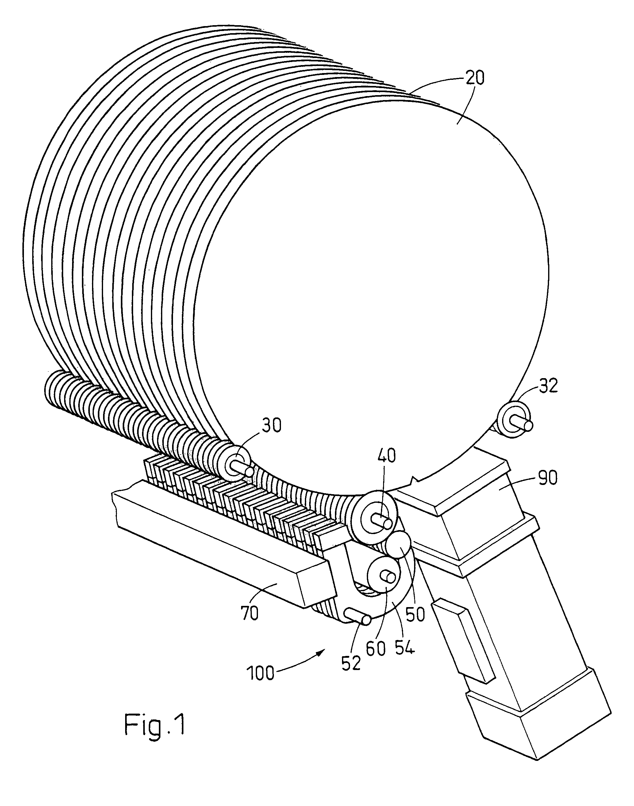
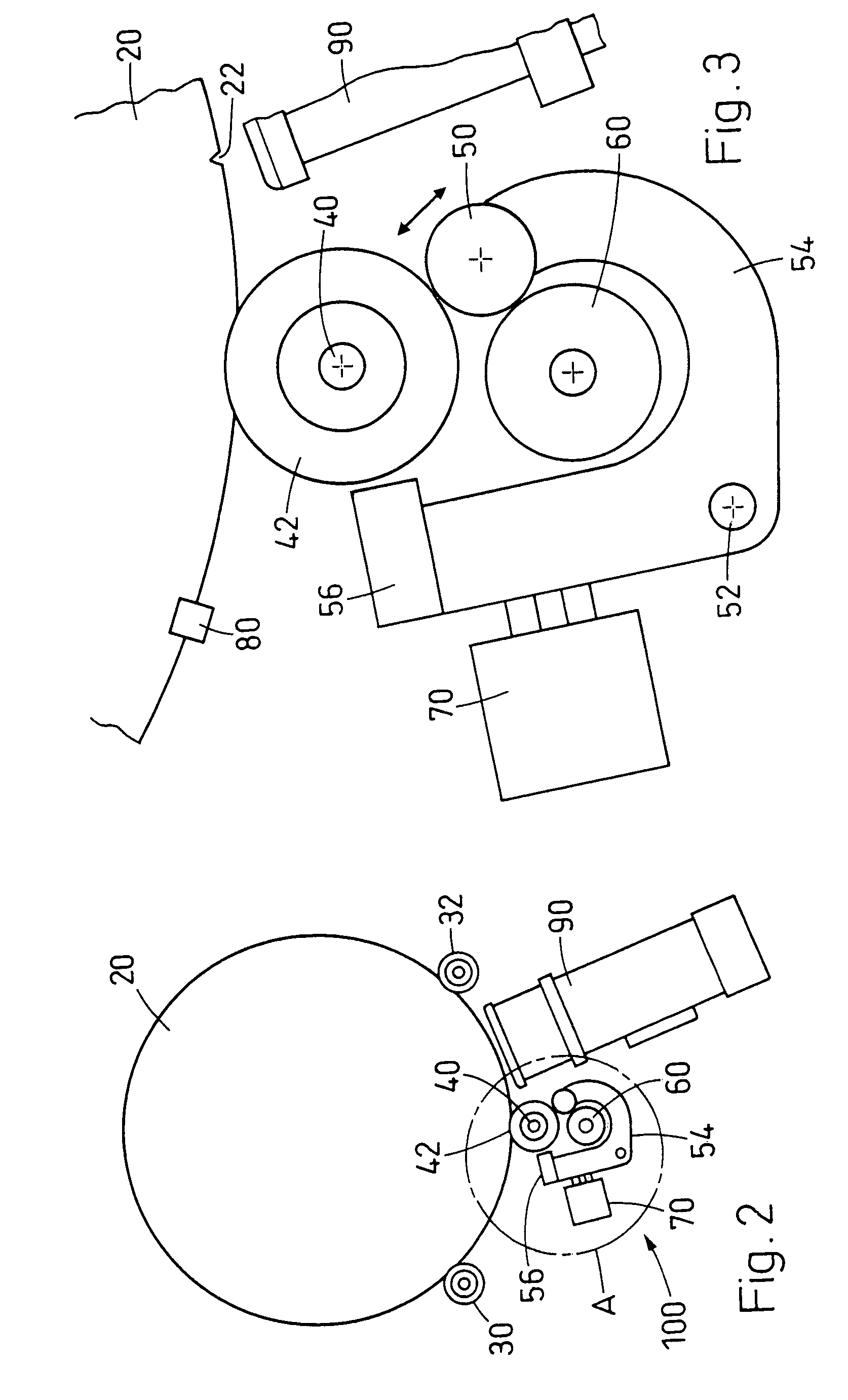
[0022]Referring to the drawings in particular, a device for positioning wafer disks is designated as a whole by 100 in FIG. 1, the wafer disks 20 are arranged on the guide rollers 34 of a first and a second mounting roller 30 and 32 such that they are held vertically in the guide rollers 34 by V notches 36. The guide rollers are mounted individually, so that a movement of a wafer disk does not induce any movement of another wafer disk.

[0023]In the first exemplary embodiment, the wafer disks are driven by the individually mounted drive roller elements 42, which are pulled over a stationary, i.e., non-rotating axle 40, always with a V notch. The drive roller elements 42 are driven selectively in the first exemplary embodiment by the rotary movement of a second drive roller 60, which is driven with an electric motor, being transmitted to the drive roller element 42 by means of a transmission roller 50. A transmission roller 50 each, one of which brings about the selective coupling, is ...


PUM


Abstract

A device for aligning a plurality of vertically arranged (upright) disks (20), especially wafer disks during the fabrication of semiconductor chips. Two mounting or bearing elements (30, 32) respectively have individually mounted guide rollers (34) positioned next to each other for each disk position. A drive device (40, 42; 50, 60; 240, 242) is for rotating the disks in relation to their azimuthal positions. A device (80) is provided for detecting the azimuthal positions of notches or indentations (22) arranged in the outer circumference in the disks (20). A device is provided for controlling the drive with the signals of the detection device (80) for detecting the azimuthal positions of the notches (22). The drive for rotating the disks in relation to their azimuthal positions has an individually driven drive roller element (42) for each disk (20) mounted on the stationary axis. In one embodiment, the drive roller elements, via a plurality of transmission rollers, can be selectively coupled to a driven roller (60) with the aid of the actuator elements. In a second embodiment, the first drive roller is individually driven by a plurality of individually controlled drive elements (240).

Description

FIELD OF THE INVENTION[0001]The present invention pertains to a device for the harmonized positioning of a plurality of wafer disks as well as to a process therefor. The present invention pertains, in particular, to a device with which a plurality of vertically positioned, approximately circular wafer disks are aligned in a harmonized manner in relation to a notch formed in the outer circumference.BACKGROUND OF THE INVENTION[0002]At a certain stage of their processing, the wafer disks introduced into the fabrication process are cut into approximately circular disks. For various reasons, which include the crystalline orientation in the plane of the disk, on the one hand, and the arrangement of markings applied, e.g., in the outer area of the wafer disks, on the other hand, it is necessary to position a batch of wafer disks in a harmonized manner in relation to their azimuthal alignment. This is carried out when the wafer disks are arranged on a device standing next to each other. Eve...

Claims


Application Information

Patent Timeline
IPC IPC(8): H01L21/673H01L21/68
CPCH01L21/68H01L21/681Y10S414/136
Inventor BLATTNER, JAKOB
Owner MURATA MASCH LTD
Why Eureka
Try Eureka