Motor drive control with a single current sensor using space vector technique

a technology of space vector and motor drive, which is applied in the direction of dynamo-electric converter control, electronic commutator control, dynamo-electric gear control, etc., can solve the problem of the maximum fundamental phase voltage that can be produced, and achieve the effect of increasing the maximum available power output of the motor and reducing the amount of computation

Inactive Publication Date: 2008-04-03
TRW LIMITED +1
View PDF6 Cites 41 Cited by
  • Summary
  • Abstract
  • Description
  • Claims
  • Application Information

AI Technical Summary

Benefits of technology

[0004] It is an aim of the invention to maximize the magnitude of the fundamental phase voltage produced by a single current sensor drive system.
[0006] The present invention further provides a drive system for a multi-phase brushless motor comprising a plurality of phases, the system comprising a drive circuit including switch means for varying the electric potential applied across each of the windings by switching the drive circuit between a plurality of states, a current sensor connected such that it can sense the instantaneous total current flowing through the windings, and control means arranged to provide pulse width modulated drive signals to control the switch means so as to control the time that the drive circuit switches between said states in each of a series of pulse width modulation periods, wherein there is a dead time associated with switching each of the phases and the control means is arranged such that, in a period during which the circuit is in a first state for a first state time and two other states for respective shorter state times, a gap left between the two shorter state times of sufficient length to avoid overlap of their associated dead times. This means that, at high voltage demands, the occurrence of zero-volt states between the two shorter state times can be avoided.
[0010] The present invention still further provides a drive system for a multi-phase brushless motor comprising a plurality of phases, the system comprising a drive circuit including switch means for varying the electric potential applied to each of the phases by switching the drive circuit between a plurality of states, a current sensor connected such that it can sense the instantaneous total current flowing through the windings, and control means arranged to provide pulse width modulated drive signals to control the switch means so as to control the time that the drive circuit switches between said states in each of a series of pulse width modulation periods, wherein the control means is arranged to control the switching times of the switch means so that sufficient time is spent in a sufficient number of active states for the current in each of the phases to be determined by means of the current sensor, and the control means is arranged to inhibit a change, between two adjacent periods, of the order in which the switch means are switched within said periods, when the demanded voltage is low, but to allow such change of order when the demanded voltage is high. This can avoid rapid re-ordering of the states within successive PWM periods which can otherwise produce noise and vibration in the motor.
[0011] The present invention still further provides a drive system for a multi-phase brushless motor comprising a plurality of phases, the system comprising a drive circuit including switch means for varying the electric potential applied to each of the phases by switching the drive circuit between a plurality of states, a current sensor connected such that it can sense the instantaneous total current flowing through the windings, and control means arranged to provide pulse width modulated drive signals to control the switch means so as to control the time that the drive circuit switches between said states in each of a series of pulse width modulation periods, wherein the control means is arranged to control the switching times of the switch means so that sufficient time is spent in a sufficient number of active states for the current in each of the phases to be determined by means of the current sensor, and the control means is arranged to switch each phase on at a respective on time and off at a respective off time and either the on times or the off times are at predetermined times in each period. This can help to reduce the amount of computation required as at least part of the timing is fixed for each period.
[0012] The present invention yet further provides a drive system for a multi-phase brushless motor comprising a plurality of phases, the system comprising a drive circuit including switch means for varying the electric potential applied to each of the phases by switching the drive circuit between a plurality of states, a current sensor connected such that it can sense the instantaneous total current flowing through the windings, and control means arranged to provide pulse width modulated drive signals to control the switch means so as to control the time that the drive circuit switches between said states in each of a series of pulse width modulation periods, wherein the control means is arranged to control the switching times of the switch means so that sufficient time is spent in a sufficient number of active states for the current in each of the phases to be determined by means of the current sensor, and the control means is arranged to abandon current sensing under some operating conditions so as to allow a greater range of pulse width modulation timings. This can increase the maximum available power output of the motor.

Problems solved by technology

Under certain configurations this can place constraints on the PWM pattern that limit the maximum fundamental phase voltage that can be produced.

Method used


Image

  • Motor drive control with a single current sensor using space vector technique
  • Motor drive control with a single current sensor using space vector technique
  • Motor drive control with a single current sensor using space vector technique

Examples


Embodiment Construction

System Overview

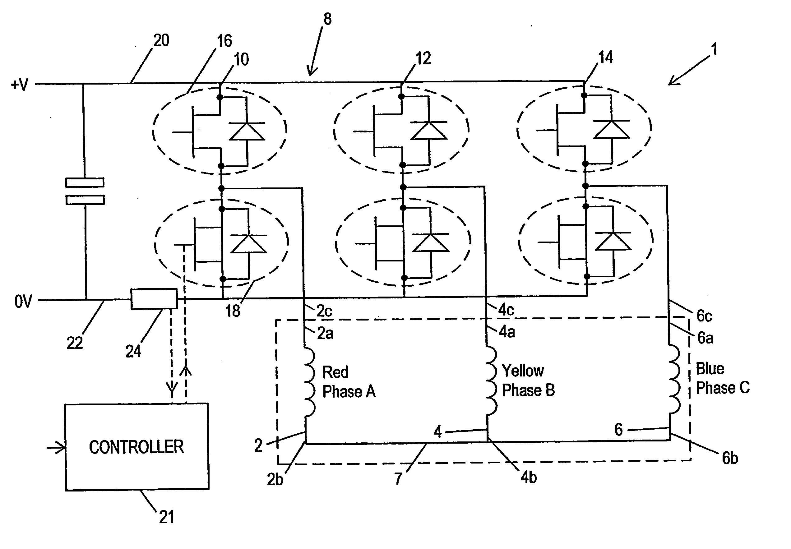
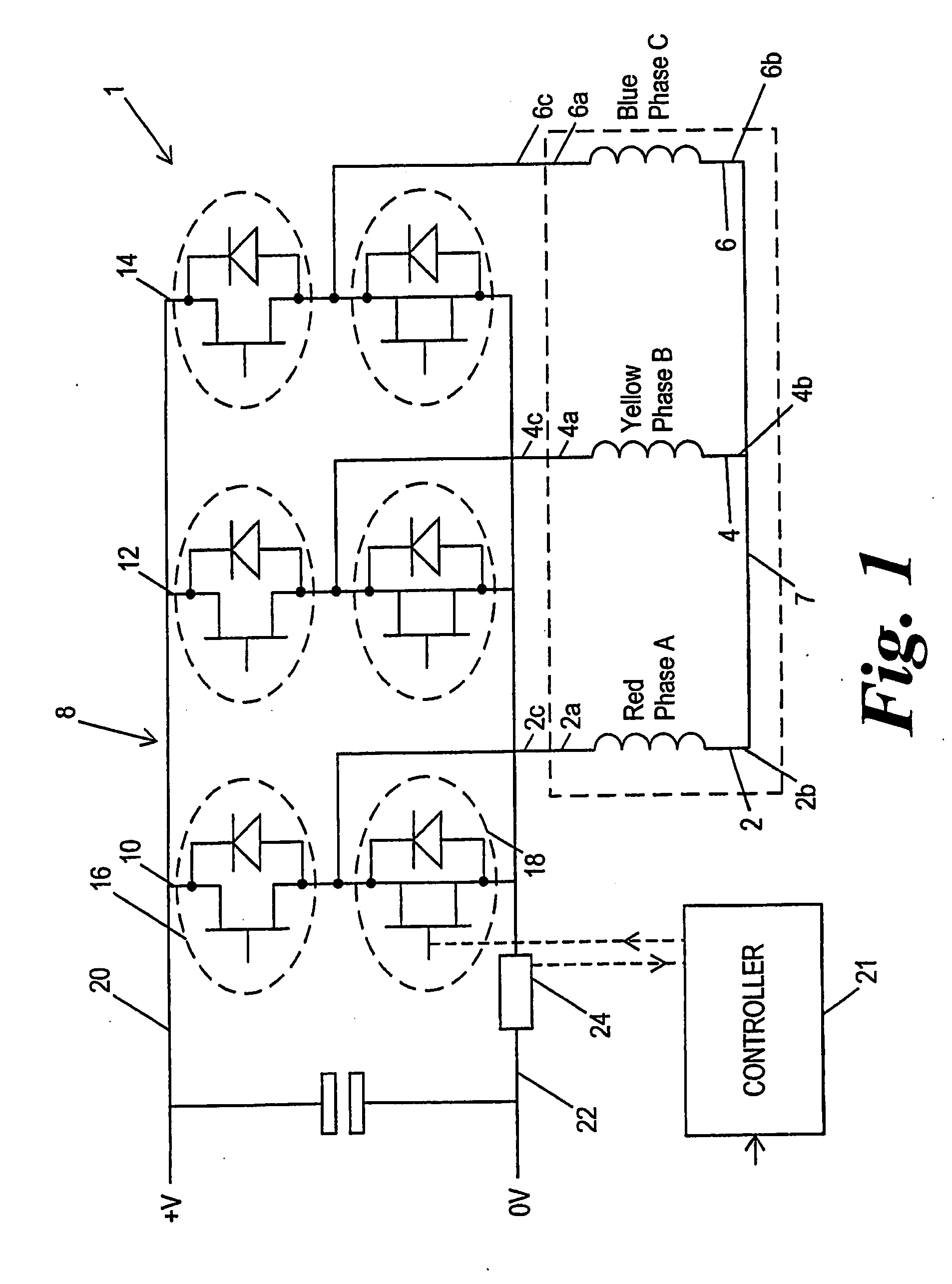
[0034] Referring to FIG. 1 a three phase brushless motor 1 comprises three motor windings 2, 4, 6, generally designated as phases A, B and C, connected in a star network. One end 2a, 4a, 6a of each coil is connected to a respective terminal 2c, 4c, 6c. The other ends 2b, 4b, 6b, of the coils are connected together to form the star centre 7. A drive circuit comprises a three phase bridge 8. Each arm 10, 12, 14 of the bridge comprises a pair of switches in the form of a top transistor 16 and a bottom transistor 18 connected in series between a supply rail 20 and ground line 22. The motor windings 2, 4, 6 are each tapped off from between a respective complementary pair of transistors 16, 18. The transistors 16, 18 are turned on and off in a controlled manner to provide pulse width modulation of the potential applied to each of the terminals 2c, 4c, 6c, thereby to control the potential difference applied across each of the windings 2, 4, 6 and hence also the current flo...


PUM


Abstract

A drive system for a three phase brushless AC motor is arranged to optimize the transistor switching pattern to improve power output whilst allowing current measurement in all of the phases using a single sensor. This is achieved by defining voltage demand vectors x where more than two states are required to meet a minimum state time requirement determined by the single sensor method, and calculating three or more state vectors which produce the demanded vector x whilst still allowing single current sensing. Various methods of optimising the PWM pattern so as to give maximum output whilst using single current sensing are also disclosed.

Description

CROSS-REFERENCE TO RELATED APPLICATIONS [0001] This application is a Divisional Application of U.S. patent application Ser. No. 11 / 006,460, filed on Dec. 7, 2004, which is a continuation of International Application No. PCT / GB03 / 02466, filed Jun. 5, 2003, which claims priority from U.K. Patent Application No. 0213098.7, filed Jun. 7, 2002. The disclosures of all of the above listed applications are incorporated herein by reference.BACKGROUND OF THE INVENTION [0002] This invention relates to electric motor control, and in particular to pulse width modulation (PWM) control of multiple phase brushless motors. [0003] Control systems for electric motors need to measure the current through the windings or phases of the motor and this can either be done by means of separate current sensors for all of the phases, or by means of a single current sensor that is placed in the circuit so as to measure the total instantaneous current flowing between a D.C. power supply and the bridge circuit and...

Claims


Application Information

Patent Timeline
Patent Type & Authority Applications(United States)
IPC IPC(8): H02P6/18H02M7/5387H02P6/08H02P21/14H02P27/06
CPCH02M7/5387H02M7/53873H02M7/53875H02M7/5395H02M2007/53876H02P23/0036H02M2001/0009H02P23/0004H02M1/0009H02M7/53876H02P21/00H02P27/08
Inventor WILLIAMS, CONNEL BRETTCOLES, JEFFREY RONALDSZABO, ADRIANDIXON, CHRISTOPHER DAVIDLI, JIANGFARDOUN, ABBAS AHMAD
Owner TRW LIMITED
Why Eureka
Try Eureka