Method for generating a trip current for triggering an electrical protection element

a technology of electrical protection element and trip current, which is applied in the direction of automatic disconnection emergency protection arrangement, circuit arrangement, electrical apparatus, etc., can solve the problem that not all electrical components can withstand the same maximum current passing through, electrical components run the risk of being damaged, and the electrical component cannot be fully functional. to achieve the effect of maximizing the magnitude of the trip curren

Active Publication Date: 2020-03-03
SOCOMEC
View PDF8 Cites 0 Cited by
  • Summary
  • Abstract
  • Description
  • Claims
  • Application Information

AI Technical Summary

Benefits of technology

[0018]The invention seeks to provide a method that makes it possible to maximize the magnitude of a trip current delivered by a power supply device until a protection element trips, while controlling the amplitude of the trip current over time as a function of the thermal inertia of the electrical components of the power supply device.
[0021]The method thus makes it possible firstly to deliver a trip current of amplitude that is as great as possible at the instant when the fault is detected, thereby maximizing the chance of tripping the protection element in the first instants following detection of the electrical fault, and secondly to maximize continuously the amount of energy that is delivered over time by the trip current until the fault is isolated from the circuit, i.e. until the protection element trips.
[0022]The way the amplitude of the trip AC signal decreases as a function of the thermal inertia of the components of the power supply device makes it possible to match the waveform of the trip signal as well as possible to the limit thermal conditions of the components of the power supply device, and thus to make full use of the performance potential of the power supply device. When the protection element is a fuse, this makes it possible in particular to deliver the maximum possible amount of heat energy from the first instants in order to cause the fuse to melt as quickly as possible and thereby isolate the power supply device from the load as soon as possible after detecting the fault situation.
[0024]The waveform of the trip current signal delivered by the method of the invention thus makes it possible to deliver a maximum value of trip current that is greater than the maximum value in either of the two above-described known solutions and to deliver a quantity of energy, corresponding to the product i2t, that is greater than in either of the two above-described known solutions. And this is made possible without having recourse to overdimensioning the inverter.
[0028]The advantage of a squarewave signal compared with any other AC signal is that the quantity of current delivered over one period is maximized compared with other waveforms for an AC signal, i.e. over one half-period, the integral of the current is greater than the integral of the current for an AC signal or a triangular signal. In other words, a square waveform serves to maximize the energy delivered over time by the trip current compared with any other AC signal waveform.

Problems solved by technology

A short circuit in a load connected to an outlet terminal of a UPS can give rise to faulty delivery of electricity by a UPS.
The main difficulty relating to generating a trip current is to be able to deliver such a current, while remaining within thermal conditions that can be withstood by the inverter, i.e. thermal conditions that avoid any degradation of the other elements of the inverter, such as its semiconductors.
Furthermore, not all of the electrical components can withstand the same maximum current passing through them.
Each component thus presents limit characteristics, and in particular a limit current or amplitude beyond which the component is damaged regardless of the length of time during which the current is applied, and a limit temperature above which the electrical component runs the risk of being damaged.
Nevertheless, the two known solutions described above do not make it possible to use all of the available capacity of the UPS for protecting electrical faults.

Method used


Image

  • Method for generating a trip current for triggering an electrical protection element
  • Method for generating a trip current for triggering an electrical protection element
  • Method for generating a trip current for triggering an electrical protection element

Examples


Embodiment Construction

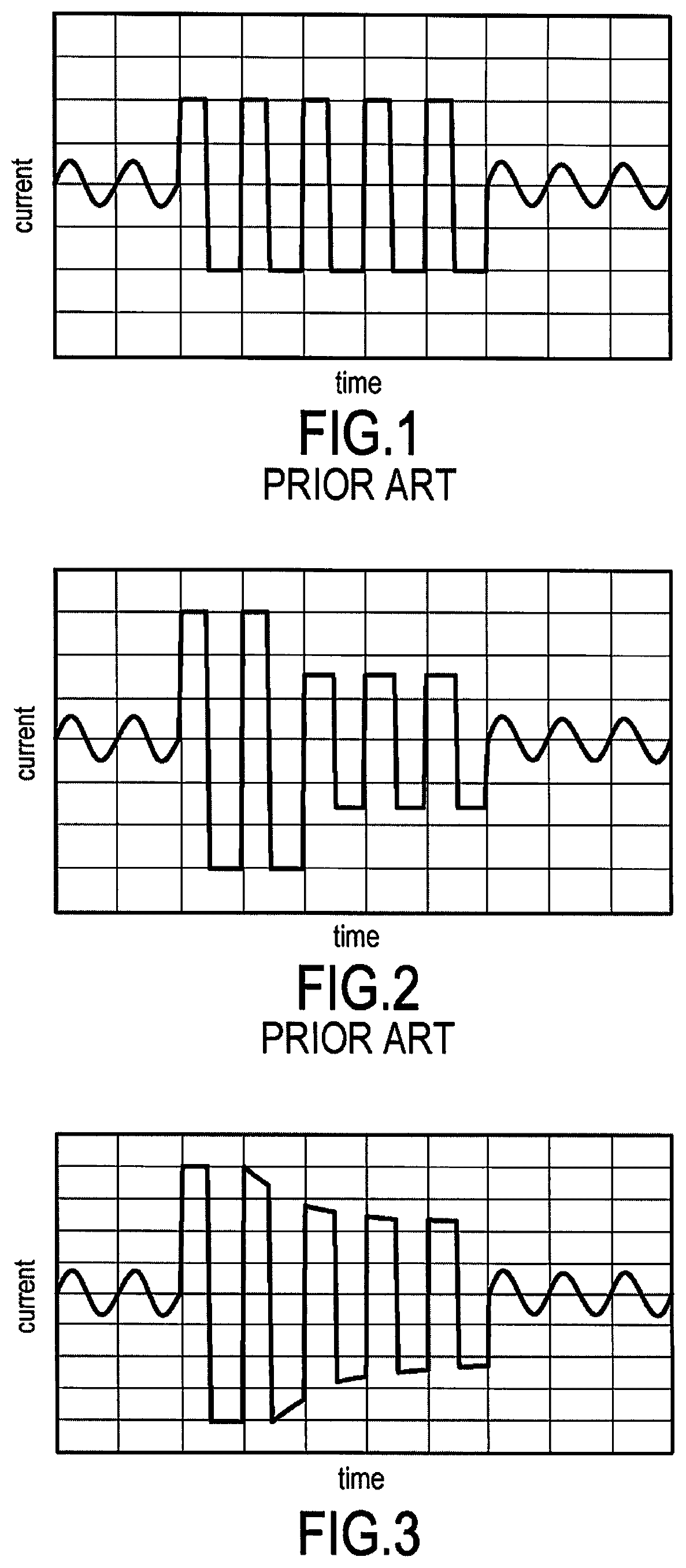
[0051]FIG. 3 shows an example of an AC signal generated in an implementation of the method of the invention.

[0052]The trip current signal is an AC signal comprising a first period having the form of a squarewave signal with a current amplitude equal to the maximum current amplitude that can be withstood by the electrical components of said power supply device.

[0053]The following periods of the trip signal present a pseudo-square waveform in that the rising and falling fronts are very steep but the crests present a decreasing shape. Periods after the first period thus present an AC signal of current amplitude that decreases as a function of the thermal inertia of said components.

[0054]Thus, for periods after the first period, not only does the amplitude of the AC signal decrease successively from one period to the next, but it also decreases within a single period of the signal, the crests of the pseudo-squarewave signal are not of respective values that are constant, but rather the ...


PUM


Abstract

A method of generating a trip current by a power supply device has electrical components and for the purpose of tripping a protection element connected between a load and the power supply device. In response to detecting an electrical fault situation in the power supply device, in order to eliminate the short-circuit fault with shortened tripping time, an AC trip current is generated having: for a first period of the signal, a current amplitude equal to the maximum current amplitude that can be withstood by the electrical components of the power supply device; and for the following periods, a current amplitude that decreases as a function of the thermal inertia of the electrical components.

Description

BACKGROUND OF THE INVENTION[0001]The invention relates to an uninterruptible power supply, and more particularly to a method of using the uninterruptible power supply device to generate a trip current for the purpose of tripping a protection device located in the installation powered by the uninterruptible power supply device.[0002]An uninterruptible power source or uninterruptible power supply (UPS) is an electronic power device that serves to deliver stable alternating current (AC) without any interruptions or micro-interruptions, regardless of what happens on the electricity network.[0003]A UPS is generally used to supply electrical power to buildings such as data centers, e.g. such as centers hosting data or industrial websites.[0004]The term “inverter” is frequently misused to designate the entire device. This applies for example with the inverters that are interposed between the power supply network and servers in a computer center.[0005]A UPS is constituted by a converter, or...

Claims


Application Information

Patent Timeline
Patent Type & Authority Patents(United States)
IPC IPC(8): H02H3/08H02H3/05H02J9/06H02H3/02H02H7/122
CPCH02H3/08H02J9/06H02H3/021H02H7/1227H02H3/02H02H3/05H02H3/023
Inventor BOOS, PASCAL
Owner SOCOMEC
Why Eureka
Try Eureka