Arc-extinguishing unit structure for direct current air circuit breaker

Pending Publication Date: 2022-06-30
LS ELECTRIC CO LTD
View PDF0 Cites 0 Cited by
  • Summary
  • Abstract
  • Description
  • Claims
  • Application Information

AI Technical Summary

Problems solved by technology

Further, arc stagnation occurs between the fixed contact and the movable contact.
Further, high temperature arc stagnation causes serious structural and

Method used


Image

  • Arc-extinguishing unit structure for direct current air circuit breaker
  • Arc-extinguishing unit structure for direct current air circuit breaker
  • Arc-extinguishing unit structure for direct current air circuit breaker

Examples


first embodiment

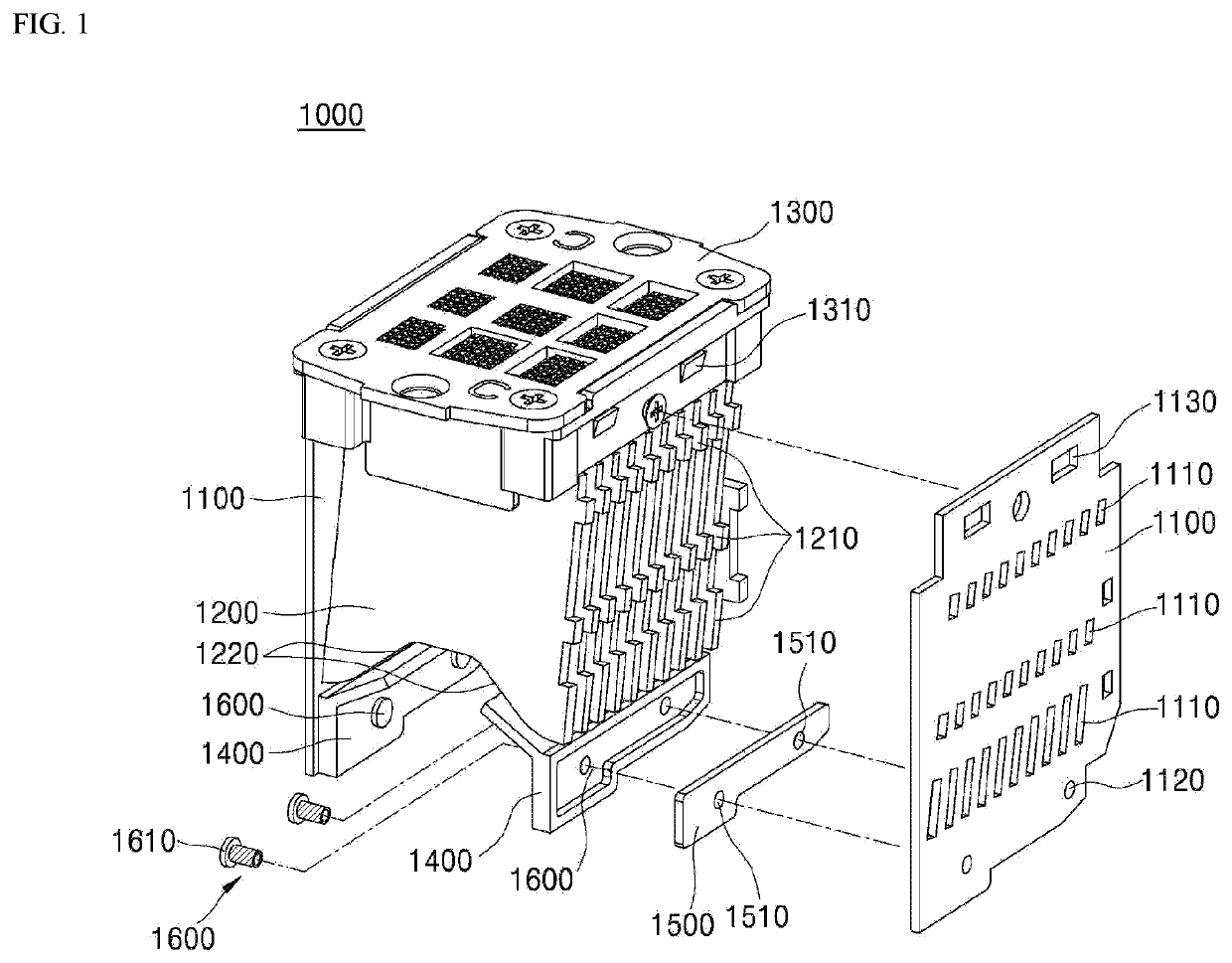
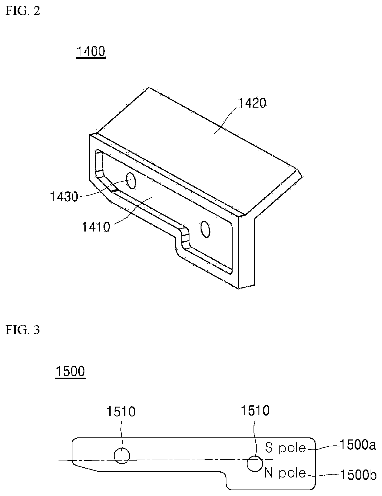
[0038]FIG. 1 is a configuration diagram schematically showing an arc-extinguishing structure for a direct-current air circuit breaker according to the present disclosure. FIG. 2 is a schematic diagram showing an arc guide in the arc-extinguishing structure shown in FIG. 1. FIG. 3 is a schematic diagram showing a magnet in the arc-extinguishing structure shown in FIG. 1.

[0039]An arc-extinguishing structure 1000 may allow a direct-current air circuit breaker used in various direct-current interruption facilities including solar power generation facilities to secure small current interruption performance.

[0040]As shown, the arc-extinguishing structure 1000 includes side plates 1100, a grid 1200, a discharge cover 1300, an arc guide 1400 and a magnet 1500.

[0041]More specifically, the grid 1200 acts as a cooling plate that divides and cools incoming arc. The grid 1200 includes a plurality of grids spaced apart from each other and disposed between both opposing side plates 1100 positioned...

second embodiment

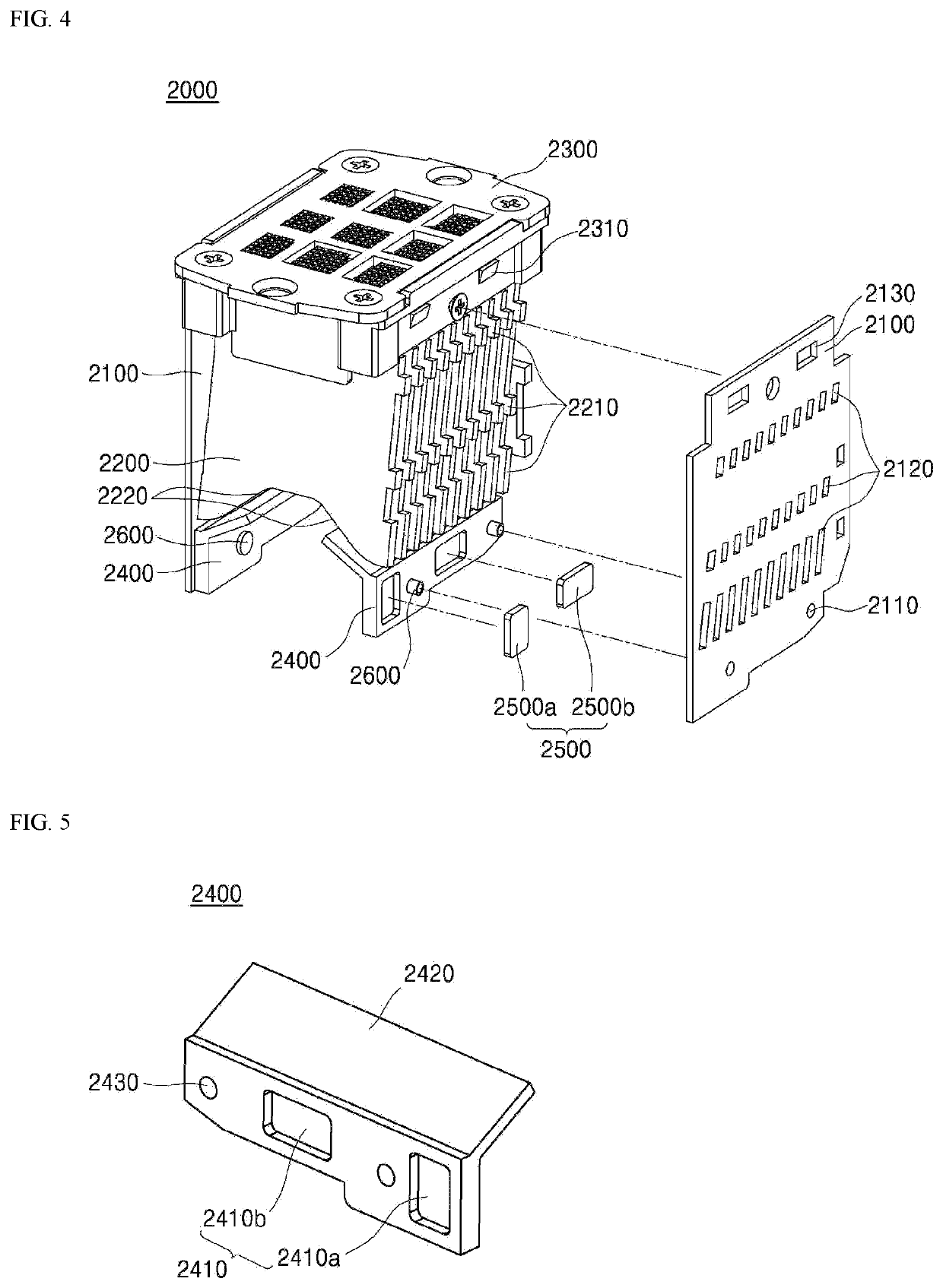
[0062]FIG. 4 is a configuration diagram schematically showing an arc-extinguishing structure for a direct-current air circuit breaker according to the present disclosure. FIG. 5 is a schematic diagram showing an arc guide in the arc-extinguishing structure shown in FIG. 4. FIG. 6 is a schematic diagram showing a magnet in the arc-extinguishing structure shown in FIG. 4.

[0063]As shown, an arc-extinguishing structure 2000 differs from the arc-extinguishing structure 1000 shown in FIG. 1 to FIG. 3 only in terms of the magnet and the magnet receiving groove 1410 accommodating therein the magnet.

[0064]More specifically, the arc-extinguishing structure 2000 includes both side plates 2100, a grid 2200, a discharge cover 2300, an arc guide 2400, and magnets 2500a and 2500b.

[0065]The magnet includes a first magnet 2500a and a second magnet 2500b.

[0066]In addition, the side plates 2100, the grid 2200, and the discharge cover 2300 are respectively identical with the side plates 1100, the gri...


PUM


Abstract

An arc-extinguishing unit structure for a direct current air circuit breaker according to one embodiment of the present disclosure comprises: a plurality of grids; side plates coupled to both sides of the plurality of grids so that the plurality of the grids are mounted so as to be spaced apart from each other; an exhaust cover positioned above the side plates and the plurality of grids; an arc guide coupled to the side plates so as to be located under the plurality of grids; a magnet coupled to the arc guide, wherein the magnet is magnetized with different poles on the basis of the plurality of grids and the vertical orientation of the arc guide.

Description

FIELD[0001]The present disclosure relates to an arc-extinguishing structure for a direct-current air circuit breaker.DESCRIPTION OF RELATED ART[0002]In general, an air circuit breaker (ACB) is installed in a low voltage distribution line and performs transmission, switching, switching, and stop of low voltage system power in a planned manner, and uses air as extinguishing medium to break a circuit in an event of abnormalities such as overcurrent, short circuit and ground fault and thus protect people and a load.[0003]More specifically, a direct-current air circuit breaker according to a prior art includes an extinguishing part and an electrical conducting part inside the circuit breaker. When abnormal current occurs due to overcurrent, short circuit, or ground fault of a line, a mechanical part operates via a relay such that a fixed contact and a movable contact are removed from each other.[0004]Further, an arc is generated when the fixed contact and the movable contact are removed ...

Claims


Application Information

Patent Timeline
IPC IPC(8): H01H33/18H01H33/53
CPCH01H33/182H01H33/53H01H9/443H01H9/30H01H9/362H01H73/18H01H31/02
Inventor KIM, IL-HYUN
Owner LS ELECTRIC CO LTD
Why Eureka
Try Eureka