Electric energy charging control apparatus and method for hybrid vehicle

a technology of electric energy charging and control apparatus, which is applied in the direction of engine-driven generators, electric devices, machines/engines, etc., can solve the problems of small amount of energy that can be charged into the battery, natural reduction of battery capacity, and inability to discharge the amount that is needed

Inactive Publication Date: 2002-02-05
TOYOTA JIDOSHA KK
View PDF8 Cites 101 Cited by
  • Summary
  • Abstract
  • Description
  • Claims
  • Application Information

AI Technical Summary

Benefits of technology

According to this construction, if it is predicted that the electric energy storage device will be discharged in the future, the target amount of charge of the electric energy storage device is changed to an increased value to increase the amount of charge beforehand, so that when the discharging occurs, an increased amount of discharge from the electric energy storage device can be provided. Conversely, if it is predicted that the electric energy storage device will be charged in the future, the target amount of charge of the electric energy storage device can be changed to a reduced value to reduce the amount of charge beforehand, so that when the charging occurs, an increased amount of charge into the electric energy storage device can be achieved. Therefore, a substantial electric energy charging / discharging range can be expanded. As a result, it becomes possible to efficiently perform charging / discharging as requested while allowing a size reduction of the electric energy storage device.
In the above-described aspect, the controller may predict the future state of the charge / discharge of the electric energy storage device based on a state of the run of the vehicle, and may increase the target value of charge when the state of the run of the vehicle is a state where it is predicted that at least a predetermined amount is discharged from the electric energy storage device, and the target value changing means may reduce the target value of charge when the state of the run of the vehicle is a state where it is predicted that at least a predetermined amount will be charged into the electric energy storage device.
The controller performs prediction regarding the charge / discharge of the electric energy storage device based on, for example, vehicle speed information. For example, if a low vehicle speed continues for a predetermined time, it is predicted that the vehicle will be stopped or greatly accelerated in the future. In association with a stop or a great acceleration, a large amount of electric energy will be consumed by the electric motor function of the motor-generator. Therefore, the target amount of charge of the electric energy storage device is increased to secure a sufficient amount of charge beforehand. Conversely, if a high vehicle speed continues for a predetermined time, it is predicted that the vehicle will be decelerated in the future. At the time of a deceleration, a great amount of regenerative energy will be obtained by the power generating function of the motor-generator. Therefore, the target amount of charge is reduced to increase the region for recovery of regenerative energy beforehand, so that regenerative energy will be sufficiently recovered. This construction makes it possible to efficiently perform charging / discharging as requested while allowing a size reduction of the electric energy storage device.
According to this construction, if the vehicle ambient temperature is low, for example, below the freezing point, the target value of charge is increased so as to compensate for a reduction in the charging / discharging efficiency of the electric energy storage device caused by low temperature. Therefore, it is possible to efficiently perform charging / discharging as requested while allowing a size reduction of the electric energy storage device.

Problems solved by technology

If a battery is reduced in size, the battery capacity naturally reduces.
In that case, therefore, a problem arises when the battery is to be charged or discharged.
As a result, it becomes impossible to discharge an amount that is needed at the time of a vehicle start or acceleration.
A problem also arises at the time of deceleration.
That is, only a small amount of energy can be charged into the battery although a large amount of regenerative electric power is generated.
Thus, the amount of electric energy generated cannot be sufficiently utilized, and efficient utilization of energy (battery) cannot be realized.
Furthermore, the chemical reactions that occur inside batteries become slow when the battery ambient temperature decreases.
Therefore, at low temperatures, the charging / discharging efficiency decreases, and sufficient charging / discharging becomes impossible even when the state of charge has converged to a target SOC.
Thus, the conventional art cannot meet the demand for a battery size reduction.

Method used


Image

  • Electric energy charging control apparatus and method for hybrid vehicle
  • Electric energy charging control apparatus and method for hybrid vehicle
  • Electric energy charging control apparatus and method for hybrid vehicle

Examples


Embodiment Construction

A preferred embodiment of the invention (hereinafter, referred to as "embodiment") will be described hereinafter with reference to the accompanying drawings.

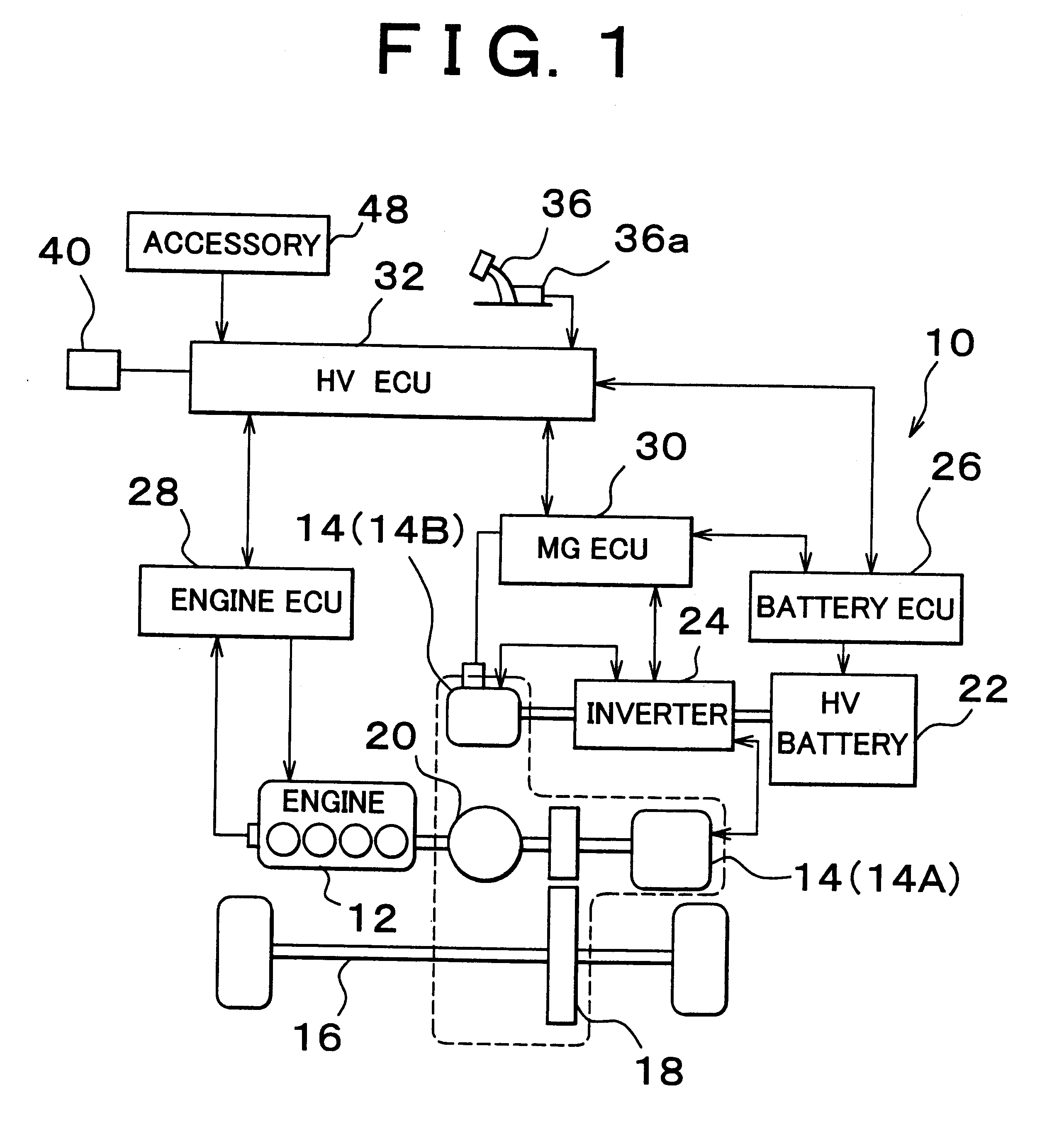
FIG. 1 shows a conceptual diagram of a construction of a hybrid vehicle (HV) 10 in accordance with the embodiment of the invention. The hybrid vehicle 10 includes, as drive power sources, an internal combustion engine (hereinafter, simply referred to as "engine"), for example, a gasoline engine, a diesel engine, etc., and a motor-generator (MG) 14. In FIG. 1, the MG 14 is illustrated as an electric motor 14A and a generator 14B for the sake of convenience in illustration. However, in accordance with the running state of the hybrid vehicle 10, the electric motor 14A can function as a generator, and the generator 14B can function as an electric motor.

The hybrid vehicle 10 further includes: a speed reducer 18 for transmitting power generated by the engine 12 or the MG 14 toward a wheel side 16 and transmitting the drive power from ...


PUM

PropertyMeasurementUnit
speedaaaaaaaaaa
speedaaaaaaaaaa
temperatureaaaaaaaaaa

Abstract

A controller predicts a requested state of charge / discharge corresponding to a future run of a hybrid vehicle. If it is predicted that the hybrid vehicle will be stopped and restarted, or will be greatly accelerated and therefore that a request for a great discharge will be outputted in the future, the controller increases a target SOC of an HV battery to increase the value to which the charge of the HV battery will be converged in preparation for the great discharge. If it is predicted that a great regenerative electric power will be generated by a vehicle deceleration and therefore that a request for charging will be outputted, the target SOC is reduced, and the amount of charge in the HV battery is reduced, so that the regenerative power generated can be efficiency recovered.

Description

INCORPORATION BY REFERENCEThe disclosure of Japanese Patent Application No. 2000-082748 filed on Mar. 23, 2000 including the specification, drawings and abstract is incorporated herein by reference in its entirety.1. Field of the InventionThe invention relates to electric energy charging control apparatus and method for a hybrid vehicle. More specifically, the invention relates to electric energy charging control apparatus and method for hybrid vehicle, that achieve efficient utilization of an electric energy storage device while allowing a size reduction of the electric energy storage device in a hybrid vehicle that needs a large amount of electric energy output in order to assist the running of the vehicle through the use of a motor-generator.2. Description of the Related ArtVehicles equipped with hybrid vehicle (HV) systems that achieve great advantages in environmental protection and fuel economy improvement (hereinafter, referred to as "hybrid vehicles (HV)") are being develope...

Claims


Application Information

Patent Timeline
Patent Type & Authority Patents(United States)
IPC IPC(8): B60K6/00B60L11/12B60L11/18B60K6/04B60L15/20B60L11/02F02D29/02B60K6/20B60K6/445B60L3/00B60L50/15B60W10/08B60W10/26B60W20/00H01M10/44H02J7/00H02J7/14
CPCB60K6/48B60L15/2045B60L2240/662B60W10/08B60W10/26B60W20/00B60W50/0097B60W2510/244B60W2510/305B60W2520/10B60W2530/00B60L50/16B60L50/61B60L58/12B60W2555/20Y02T10/62Y02T10/64Y02T10/70Y02T10/7072Y02T10/72Y02T90/16Y10S903/903B60W10/24B60W20/10B60W2710/244
Inventor SUZUKI, NAOTO
Owner TOYOTA JIDOSHA KK
Why Eureka
Try Eureka