Charging Control Unit and Method of Adjusting a Distance for an Inductive Charging Process

a charging control and electric vehicle technology, applied in the direction of cycle equipment, instruments, transportation and packaging, etc., can solve the problems of insufficient consideration of optimal distance, considerable additional weight, and criticism of the practical application of such devices, and achieve the effect of optimal charging capacity

Inactive Publication Date: 2014-04-03
SIEMENS AG
View PDF3 Cites 27 Cited by
  • Summary
  • Abstract
  • Description
  • Claims
  • Application Information

AI Technical Summary

Benefits of technology

[0017]One or more of the present embodiments provides connection of suspension controls with charging controls to provide an inductive charging process with optimal charging capacity without the provision of any additional mechanical device.

Problems solved by technology

Current concepts take insufficient account of optimal distance.
The practical application of such devices, meanwhile, has received much criticism, as comparable adjusting devices mounted on the underside of electric vehicles include extensive safety mechanisms and represent considerable additional weight.
There has thus been little enthusiasm for further development of the adjusting devices described.
Alternative adjustable devices provided on the charging station require high levels of maintenance and are susceptible to weathering, so are technically unsuitable.

Method used


Image

  • Charging Control Unit and Method of Adjusting a Distance for an Inductive Charging Process
  • Charging Control Unit and Method of Adjusting a Distance for an Inductive Charging Process

Examples


Embodiment Construction

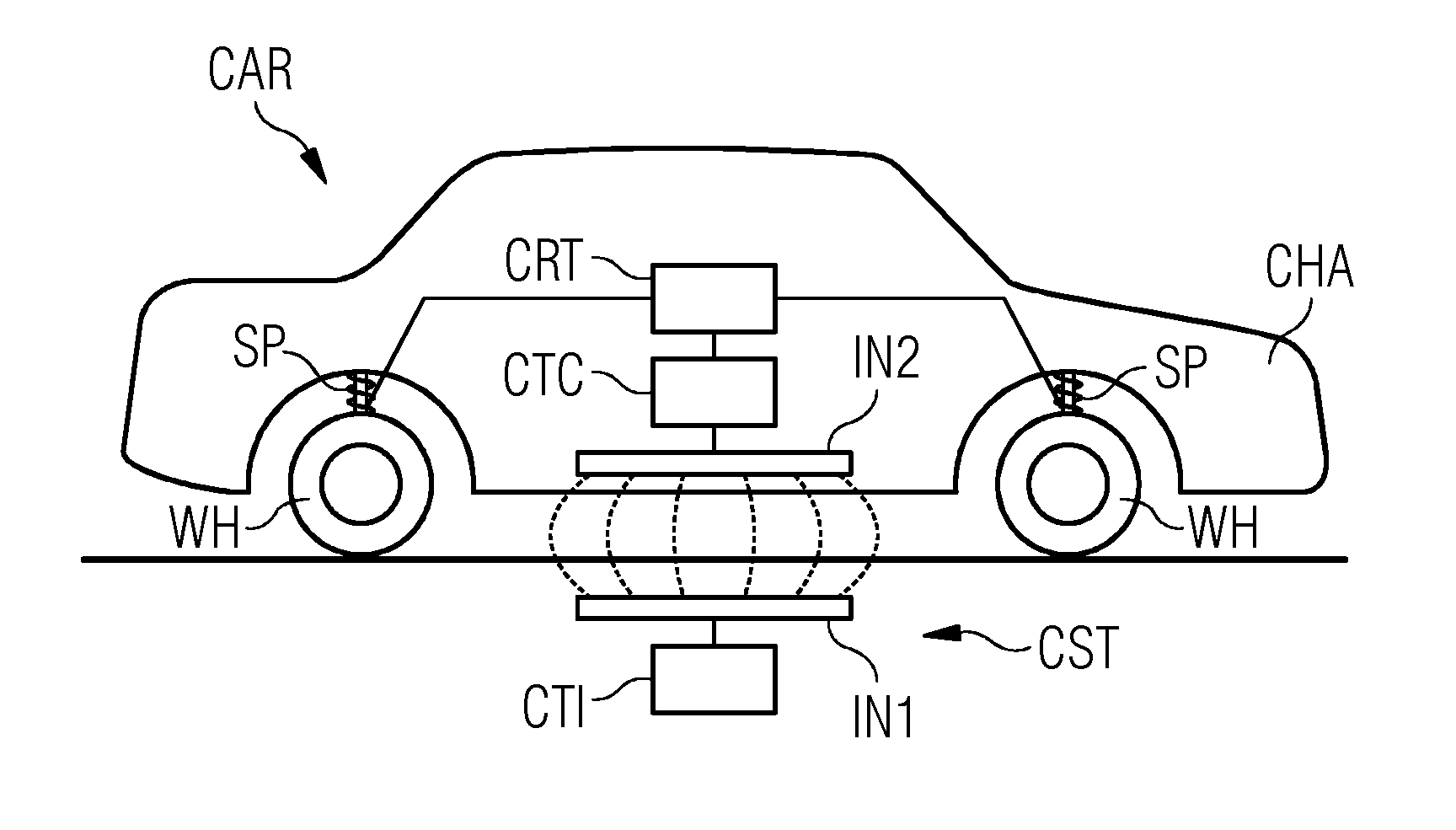
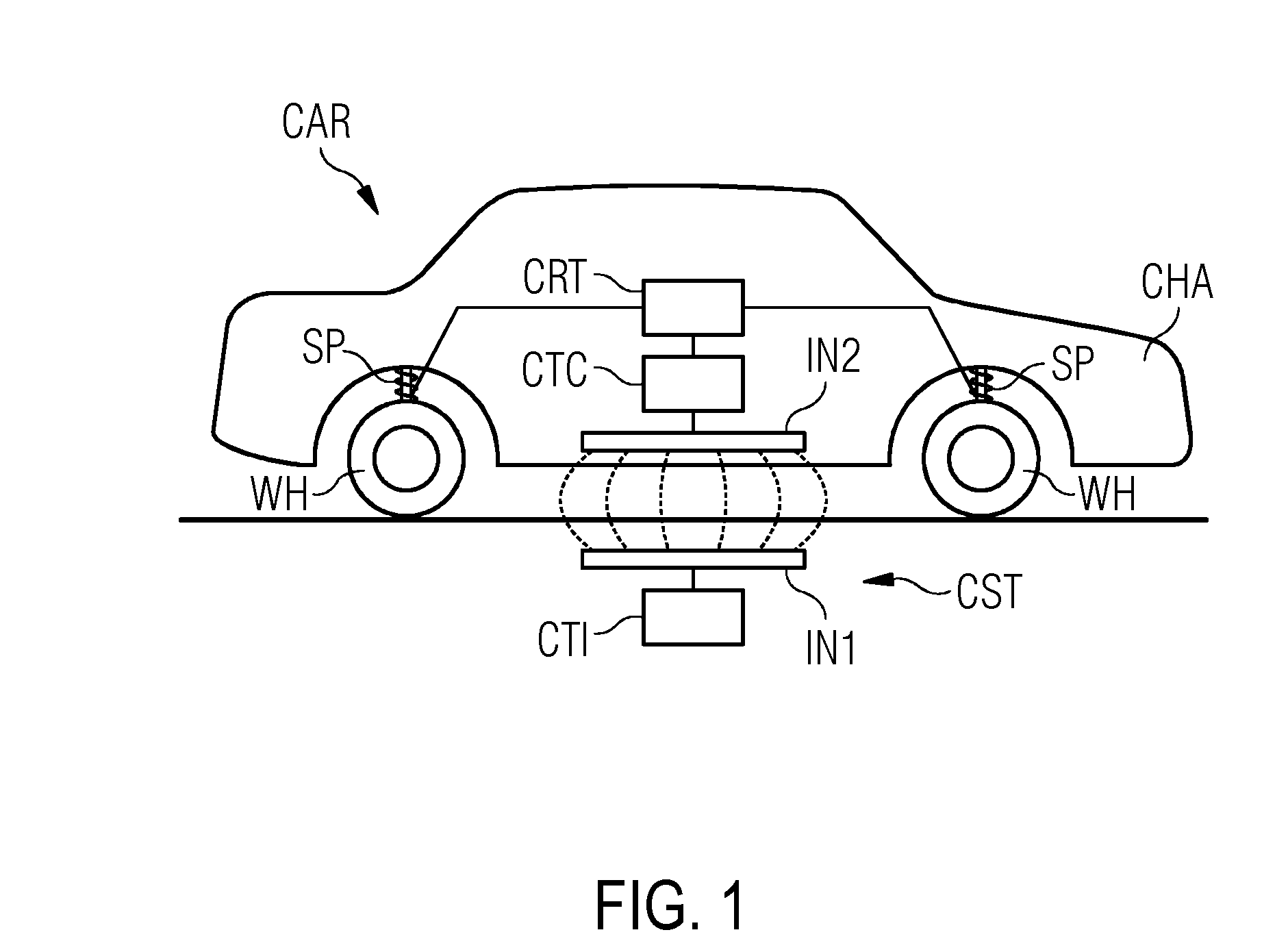
[0020]FIG. 1 shows one embodiment of a two-axled electric vehicle CAR with four wheels WH, positioned above an inductive charging station CST. The inductive charging station CST is disposed essentially below a shelf of the electric vehicle CAR and includes a first coil system IN1 and a charging control unit CTI as part of the charging station CST. Energy from the first coil system IN1 is transferred to a coil system IN2 assigned to the electric vehicle CAR via an alternating inductive field.

[0021]On an electric vehicle CAR, suspension elements SP of the electric vehicle CAR are disposed between bodywork CHA and wheel suspensions of vehicle wheels WH. The suspension elements SP retain the bodywork CHA above the wheels WH.

[0022]The electric vehicle CAR has an active suspension system, the traditional mechanical components of which, such as steel springs and shock absorbers, are replaced by suspension elements SP with which the position of the electric vehicle may be adjusted with the ...


PUM


Abstract

A method of setting an optimized distance for inductive charging between a coil system of an inductive charging station and a coil system of an electric vehicle includes determining, by the inductive charging station, the optimized distance and calculating position data based on the optimized distance determined. The method also includes transferring the calculated position data to the electric vehicle and calculating a suspension construction for the electric vehicle based on the position data. The method includes transferring data on the calculated suspension construction to a suspension control device of the electric vehicle.

Description

[0001]This application claims the benefit of DE 10 2012 217 779.5, filed on Sep. 28, 2012, which is hereby incorporated by reference.BACKGROUND[0002]The present embodiments relate to a charging control unit and a method of adjusting a distance for an inductive charging process of an electric vehicle.[0003]A charging cable may be used for charging electric vehicles at charging stations. Another known possibility for charging an electric vehicle is offered by inductive charging stations, whereby a system of coils is located both on, for example, the underside of the electric vehicle and in the charging station on the ground. Energy is transferred inductively from the charging station to the vehicle via an alternating magnetic field penetrating the coil system.[0004]An inductive charging process may be carried out following positioning of the electric vehicle on the charging station without it being necessary for the driver of the vehicle to get out or for connection to a charging cabl...

Claims


Application Information

Patent Timeline
Patent Type & Authority Applications(United States)
IPC IPC(8): B60L11/18
CPCB60L11/1829B60L53/126B60L53/36B60L53/38Y02T10/70Y02T10/7072Y02T90/12Y02T90/14
Inventor FREITAG, GUNTERKUHN, KARL JOSEF
Owner SIEMENS AG
Why Eureka
Try Eureka