Endo-cavity focused ultrasound transducer

a focused ultrasound and transducer technology, applied in the field of endocavity focused ultrasound transducers, can solve the problems of limiting the size of the transducer, limiting the acoustic energy focused at a location deep within the body, and at least partially blocking the acoustic path to a target tissue region

Inactive Publication Date: 2007-08-23
INSIGHTEC
View PDF99 Cites 159 Cited by
  • Summary
  • Abstract
  • Description
  • Claims
  • Application Information

AI Technical Summary

Benefits of technology

[0011] In accordance with yet another aspect of the present invention, an apparatus is provided for delivering acoustic energy to a target site adjacent a body passage that includes a first member including a proximal end, a distal having a size and shape for insertion into a body passage, and a first transducer carried on the distal end. The apparatus also includes a second member also including a proximal end, a distal having a size and shape for insertion into the body passage, and a second transducer carried on the distal end. The first and / or second members include one or more connectors for substantially securing the first and second members relative to one another such that the first and second transducers together at least partially define a transducer array.

Problems solved by technology

Because ultrasonic transducers are generally disposed adjacent to the patient, however, the acoustic path to a target tissue region may be at least partially obstructed, e.g., by anatomical objects such as bones or cavities, within the patient's body.
Furthermore, acoustic energy may not be adequately focused at a location deep within a body, e.g., because the resulting focal zone may be too large to provide an effective and safe treatment.
Natural body passages, however, may limit the size of the transducer that may be introduced.
The size of a transducer that may be delivered inside a body passage may be limited by the size of a body orifice at the entry point for the transducer.
For example, the size of a transducer used for treating prostate cancer may be limited by the maximum perimeter of the rectal orifice.

Method used


Image

  • Endo-cavity focused ultrasound transducer
  • Endo-cavity focused ultrasound transducer
  • Endo-cavity focused ultrasound transducer

Examples


Embodiment Construction

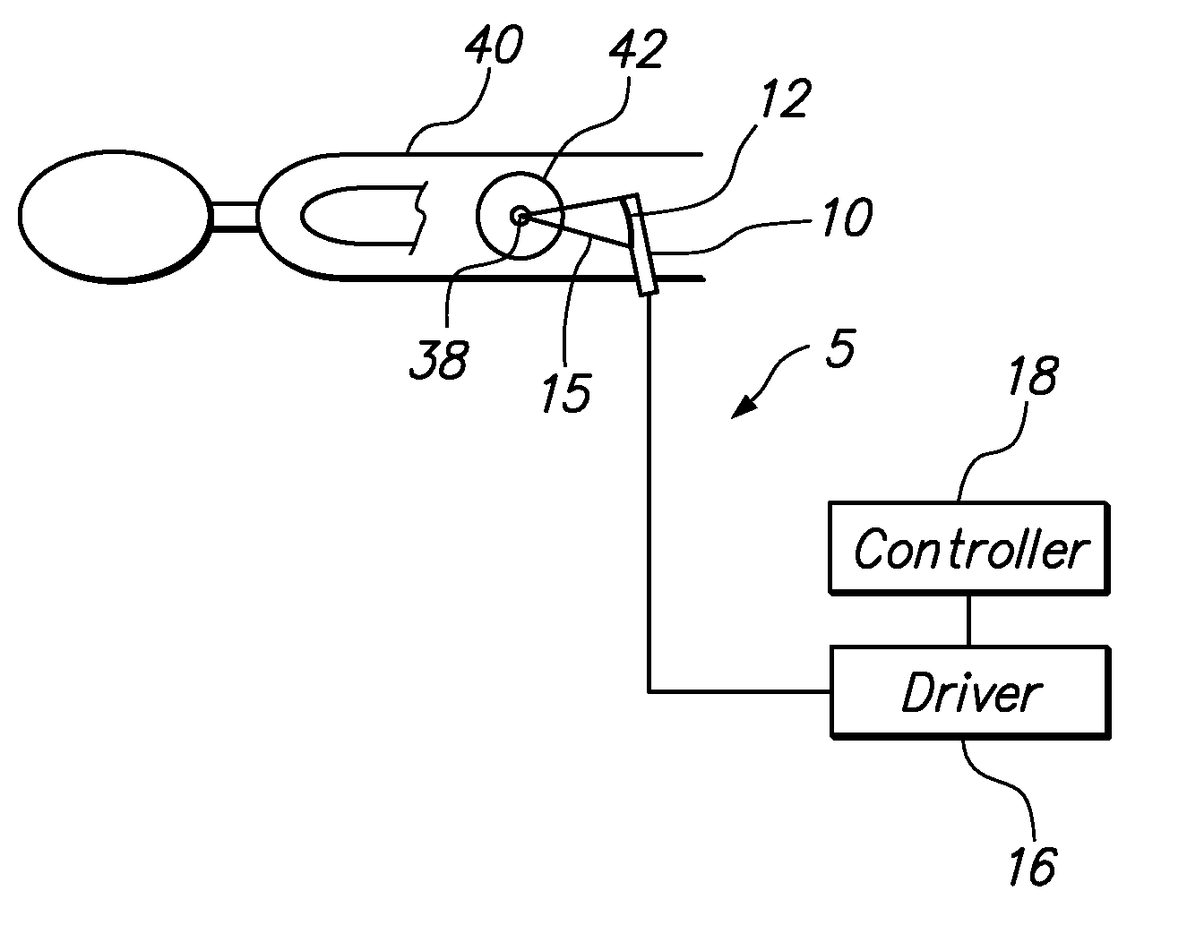
[0025] Turning to the drawings, FIG. 1 shows an exemplary embodiment of a focused ultrasound system 5 including a transducer device 10, drive circuitry 16 coupled to the transducer device 10, and a controller 18 coupled to the drive circuitry 16. As shown, the transducer device 10 generally may be introduced into a body passage 92 within a patient 90 and used to deliver acoustic energy (represented by beam 15) to a target tissue region 94 located adjacent the body passage 92. The acoustic energy 15 may be used to necrose, heat, or otherwise treat the target tissue region 94, which may be a benign or malignant tumor within an organ or other tissue structure (not shown).

[0026] The transducer device 10 generally includes one or more transducers 12 that are coupled to the driver 16 and / or controller 18 for generating and / or controlling the acoustic energy emitted by the transducer 12. For example, the driver 16 may generate one or more electronic drive signals, which may be controlled ...


PUM


Abstract

An apparatus for delivering acoustic energy to a target site adjacent a body passage includes first and second elongate members, each carrying one or more transducer elements on their distal ends. The first and / or second elongate members include connectors for securing the first and second elongate members together such that the transducer elements together define a transducer array. The first and second elongate members are introduced sequentially into a body passage until the transducer elements are disposed adjacent a target site. Acoustic energy is delivered from the transducer elements to the target site to treat tissue therein. In another embodiment, the apparatus includes a tubular member and an expandable structure carrying a plurality of transducer elements. The structure is expanded between a contracted configuration during delivery and an enlarged configuration when deployed for delivering acoustic energy to a target site adjacent the body passage.

Description

RELATED APPLICATION DATA [0001] This application is a continuation of U.S. application Ser. No. 10 / 452,061, filed Jun. 2, 2003, which is hereby incorporated by reference in its entirely.FIELD OF THE INVENTION [0002] The present invention relates generally to apparatus and methods for delivering acoustic energy, and more particularly to apparatus and methods for delivering diagnostic and / or therapeutic ultrasonic energy from a transducer disposed within a body of a subject. BACKGROUND [0003] Devices and systems using acoustic energy, particularly within the ultrasonic range (acoustic waves with a frequency greater than about twenty kilohertz (20 kHz), and more typically between fifty kiloHertz and five Megahertz (0.05-5 MHz)), have been used to diagnose and treat patients. For example, ultrasonic energy may be employed to obtain images of a region of a patient during a diagnostic or therapeutic procedure. In addition, ultrasound systems have been used for treating tissue, e.g., by fo...

Claims


Application Information

Patent Timeline
Patent Type & Authority Applications(United States)
IPC IPC(8): A61B8/14A61B17/00A61B17/22A61N7/00A61N7/02
CPCA61B17/2202A61B17/2251A61B2017/00274A61B2017/00477A61N2007/0078A61B2017/22028A61B2017/2253A61B2018/00547A61N7/022A61B2017/00867
Inventor VITEK, SHUKIKOPELMAN, DORON M.MEDAN, YOAVMAOR, DOV
Owner INSIGHTEC
Why Eureka
Try Eureka