
Overload protection switch

Inactive Publication Date: 2010-03-30
ZING EAR ENTERPRISE
View PDF38 Cites 18 Cited by
  • Summary
  • Abstract
  • Description
  • Claims
  • Application Information

AI Technical Summary

Problems solved by technology

Great current is likely to result in overload, which may cause danger.

Method used


Image

  • Overload protection switch
  • Overload protection switch
  • Overload protection switch

Examples


Embodiment Construction

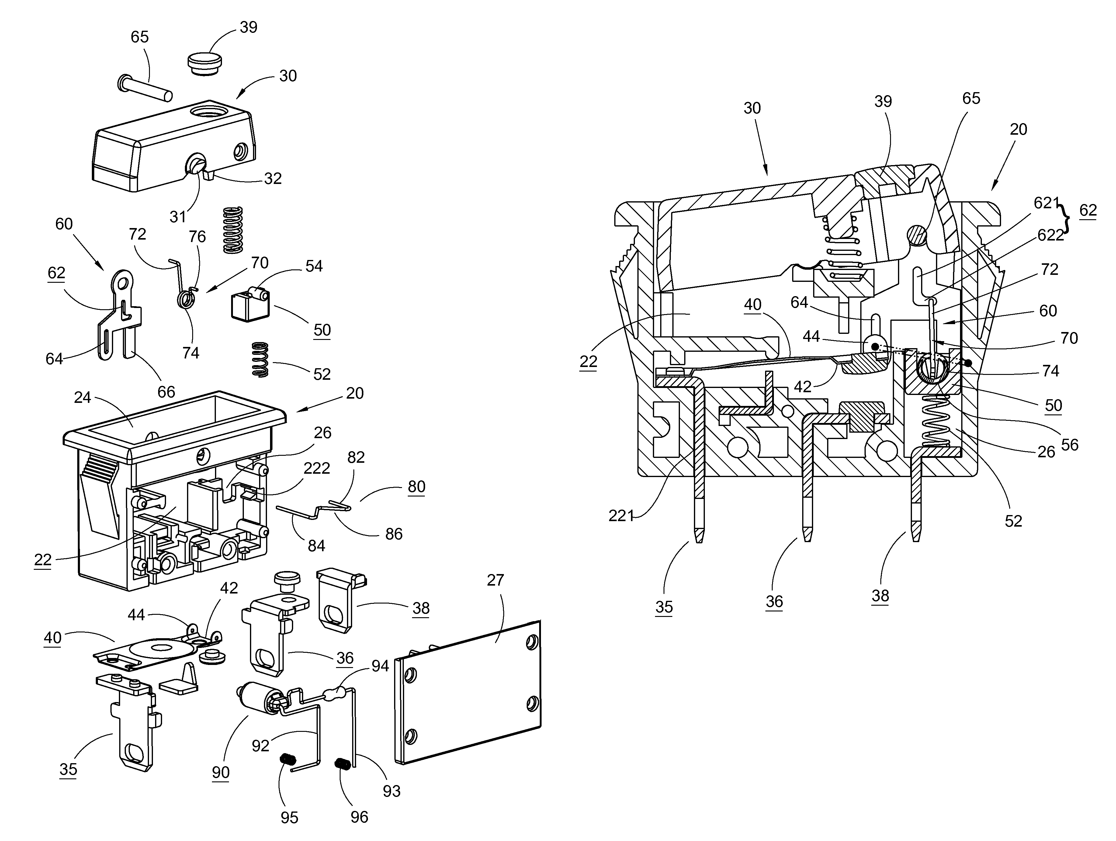
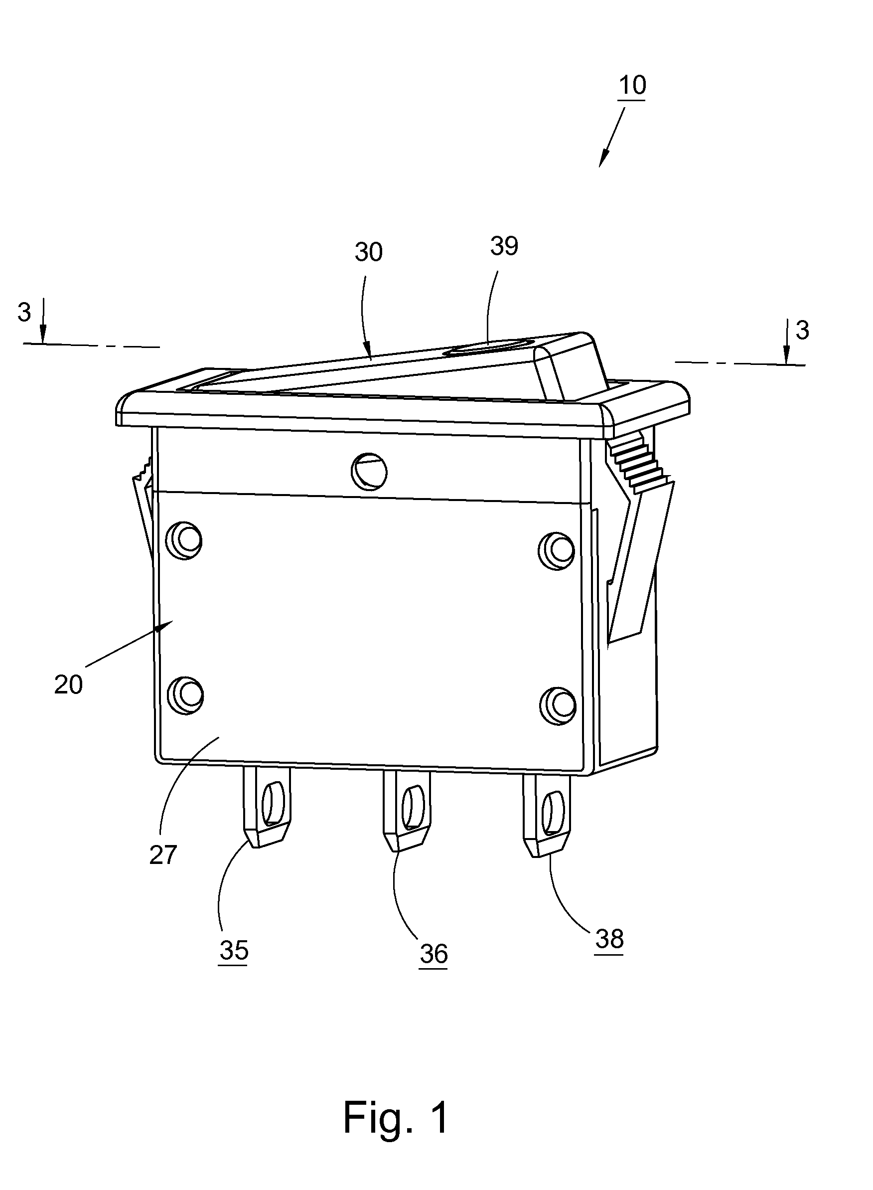
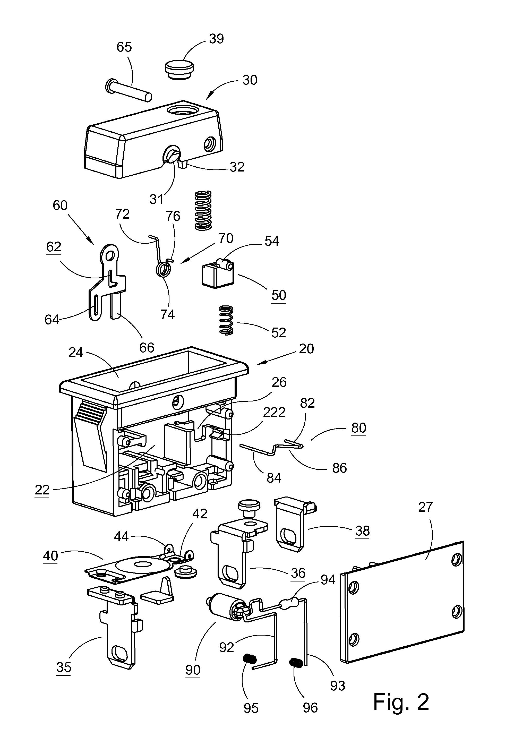
[0026]Please refer to FIGS. 1 and 2. According to a first embodiment, the overload protection switch 10 includes a main body 20, a press button 30 and components arranged in the main body 20.

[0027]The main body 20 has an internal space 22 and an opening 24 on a top face. The opening 24 communicates with the space 22. A slide way 26 is disposed in the space 22.

[0028]The press button 30 is pivotally disposed in the opening 24 of the main body 20 via a rotary shaft section 31. When pressed, the press button 30 is angularly displaced about the rotary shaft section 31. A shifting section 32 is disposed under a bottom face of the press button 30 and downward projects therefrom.

[0029]Referring to FIG. 3, a first terminal, a second terminal and a third terminal 35, 36, 38 are disposed in insertion slots 221 of the main body 20. Bottom ends of the terminals outward protrude from the main body 20. The first and third terminals 35, 38 are positioned on two sides of the main body, while the sec...


PUM


Abstract

An overload protection switch includes a main body and a press button. Several terminals, a conductive plate and other components are arranged in the main body. By means of switching the press button, the switch is switchable between an on state and an off state. In case of overload, the conductive plate will separate from one of the terminals to switch off the switch. The components arranged in the main body will not hinder the conductive plate from separating from the terminal. When switching on the switch, the conductive plate resiliently contacts the terminal. In case of overload, the conductive plate separates from the terminal to switch off the switch so as to provide overload protection effect.

Description

BACKGROUND OF THE INVENTION[0001]The present invention is generally related to a switch, and more particularly to an overload protection switch.[0002]A switch is used to control closing / opening of a circuit. Great current is likely to result in overload, which may cause danger. A switch with overload protection function is able to avoid overload of a circuit so as to avoid danger.[0003]Many kinds of overload protection switches are commercially available. It is tried by the applicant to provide an overload protection switch, which has novel structure and can be more conveniently used.SUMMARY OF THE INVENTION[0004]It is therefore a primary object of the present invention to provide an overload protection switch, which is able to provide overload for a circuit.[0005]It is a further object of the present invention to provide an overload protection switch. In case of overload, even if the press button of the switch is positioned in an on position, the switch can still automatically swit...

Claims


Application Information

Patent Timeline
Patent Type & Authority Patents(United States)
IPC IPC(8): H01H37/70H01H37/52
CPCH01H23/025H01H23/26H01H73/26H01H77/04
Inventor HUNG, TANG-YUEH
Owner ZING EAR ENTERPRISE
Learn More