Method for predicting a future voltage and/or current curve

a technology of voltage and current curve and prediction method, which is applied in the direction of relays, circuit-breaking switches, relays, etc., can solve the problems of voltage spikes, changes in the periodicity of current and voltage or else transient processes, and calculations that are required for this purpose are associated with a considerable time requirement, so as to reduce computation time and reduce computation time. , the effect of high degree of complexity

Inactive Publication Date: 2010-04-06
SIEMENS AG
View PDF9 Cites 5 Cited by
  • Summary
  • Abstract
  • Description
  • Claims
  • Application Information

AI Technical Summary

Benefits of technology

[0029]It should be noted that x[n] was used instead of y[n]. This is because exactly 2p complex data points are required, which correspond to the exponential model with the 2p complex parameters hk and zk. This relationship is expressed in equation (2.6) by minimizing the square error.
[0058]The modified Prony method is similar to the maximum likelihood principle (Gaussian principle of least squares). The calculation process is based on a fixed p (number of exponential functions, see above). During the calculation process, an iteration method is carried out, so that the accuracy of the previously determined voltage and / or current waveforms is optimized. The degree of accuracy of the previous determination can be varied by definition of tolerance limits for the optimization process. The computation time required can thus be reduced, depending on the requirement. The modified Prony method is described in detail in Osborne, Smyth: A modified Prony Algorithm for fitting functions defined by difference equations, SIAM Journal of Scientific and Statistical Computing, Vol. 12, 362-382, March 1991. The modified Prony method is insensitive to “noise” from the voltage and / or current data determined from the electrical power supply system. “Noise” such as this is unavoidable when using actual components to determine the voltage and / or current data. Interference such as this can be minimized only with an unacceptably high degree of complexity. The robustness against “noise” on the input signals makes it possible to use low-cost test equipment to determine the present voltage and / or current data in the electrical power supply system when using the modified Prony method.
[0060]Since the processes under consideration are carried out in intervals of a few milliseconds, it has been found to be advantageous to use an apparatus with a device for automated processing of the voltage and / or current data. In order to carry out this automated processing particularly quickly, it is possible to provide for the device for automated processing to be hard-wired programmed. Circuits such as these are known as application specific integrated circuits “ASICs”. However, if a sufficiently fast device for automated processing is available, then they may be in the form of programmable logic. Programmable devices such as these for automated processing can easily be matched to changing boundary conditions by reprogramming.

Problems solved by technology

In addition, voltage spikes and changes in the periodicity of the current and voltage or else transient processes can occur as a result of unpredictable events, such as switching overvoltages, which are produced when switching processes take place in the electrical power supply system, or else lightning strikes on the electrical power supply system.
The calculations that are required for this purpose are associated with a quite considerable time requirement even when using the very latest computer technology.

Method used


Image

  • Method for predicting a future voltage and/or current curve
  • Method for predicting a future voltage and/or current curve
  • Method for predicting a future voltage and/or current curve

Examples


Embodiment Construction

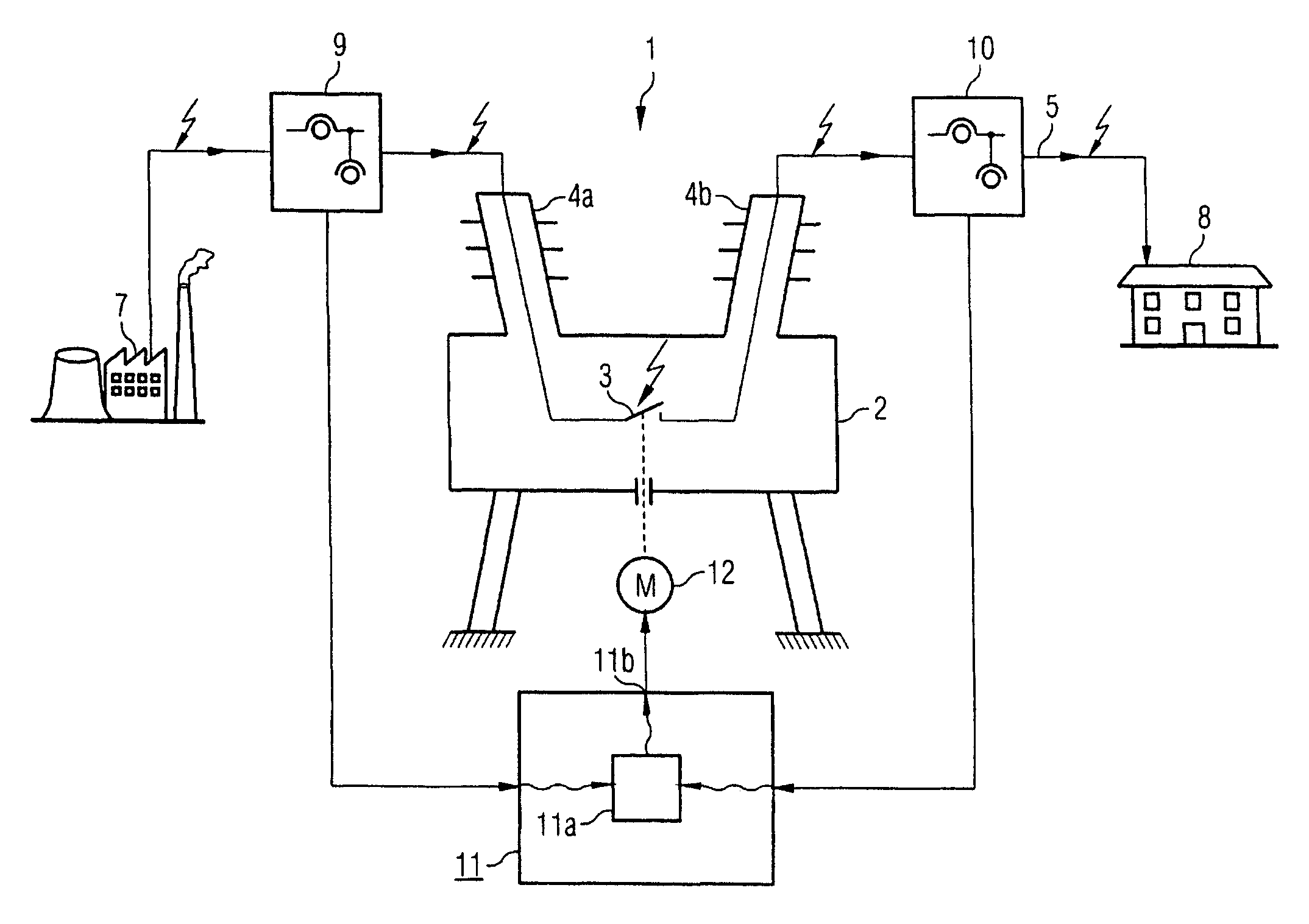
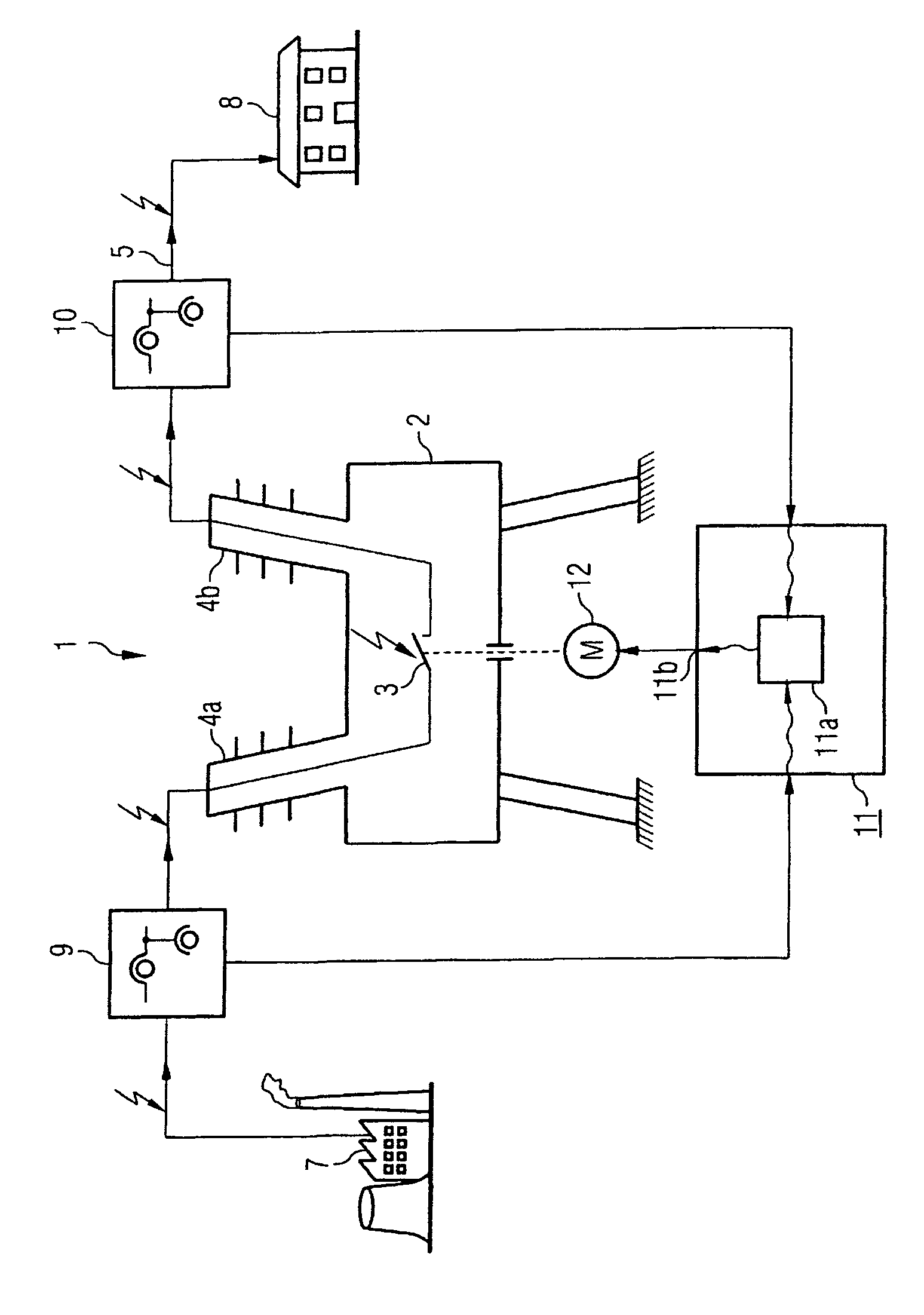
[0063]FIG. 1 shows a section through a schematically illustrated high-voltage circuit breaker 1. The high-voltage circuit breaker 1 has encapsulation 2 in which an interrupter unit 3 for the high-voltage circuit breaker 1 is arranged. The interrupter unit 3 for the high-voltage circuit breaker 1 is connected to an electrical power supply system 5 by means of high-voltage bushings 4a, b. The electrical power supply system 5 may, for example, be an overhead line power supply system for transmitting electrical power from a power station 7 to a consumer 8. A first measurement apparatus 9 is arranged upstream of the high-voltage circuit breaker 1 in the power flow direction. A second measurement apparatus 10 is arranged downstream from the high-voltage circuit breaker 1 in the power flow direction. The first measurement apparatus 9 and the second measurement apparatus 10 may, for example, comprise current transformers and voltage transformers as well as further apparatuses. It is also po...


PUM


Abstract

According to the invention, a controlled or synchronous switching of an electrical power breaker (1) can be guaranteed by means of predicting a future voltage and / or current curve from actual voltage and / or current data in an electrical energy network (5). The prediction of the future voltage and / or current curve is carried out using the voltage and / or current data determined in the electrical network (5) at different timepoints by application of a Prony method to the available voltage and / or current data.

Description

CLAIM FOR PRIORITY[0001]This application claims priority to International Application No. PCT / DE02 / 04573 which was published in the German language on Jun. 19, 2003, which claims the benefit of priority to German Application No. 101 62 118.3, which was filed in German language on Dec. 12, 2001.TECHNICAL FIELD OF THE INVENTION[0002]The invention relates to a system and method for determination of a future voltage and / or current waveform in an electrical power supply system.BACKGROUND OF THE INVENTION[0003]In electrical power supply systems, in particular power supply systems for the transmission of electrical power whose voltage changes periodically and in which the current flowing through the power supply system changes periodically, it is desirable to be able to predict future voltage and / or current waveforms. During undisturbed operation, the voltage and the current oscillate periodically at a constant frequency, with a constant amplitude, about a defined zero position. A phase sh...

Claims


Application Information

Patent Timeline
Patent Type & Authority Patents(United States)
IPC IPC(8): H01H47/02H01H33/59H01H9/56H02H1/00H02J3/00
CPCH01H9/56H02H1/0092H02H3/021
Inventor PILZ, GEORGSCHEGNER, PETER
Owner SIEMENS AG
Why Eureka
Try Eureka