Selection of obscured computer-generated objects

Active Publication Date: 2010-04-06
DASSAULT SYST SOLIDWORKS CORP
View PDF6 Cites 9 Cited by
  • Summary
  • Abstract
  • Description
  • Claims
  • Application Information

AI Technical Summary

Problems solved by technology

Modifying a visibility characteristic may cause objects to become transparent and discernable or to become invisible, and / or may cause the removal of objects from a display structure used for constructing the computer-generated model.

Method used


Image

  • Selection of obscured computer-generated objects
  • Selection of obscured computer-generated objects
  • Selection of obscured computer-generated objects

Examples


Embodiment Construction

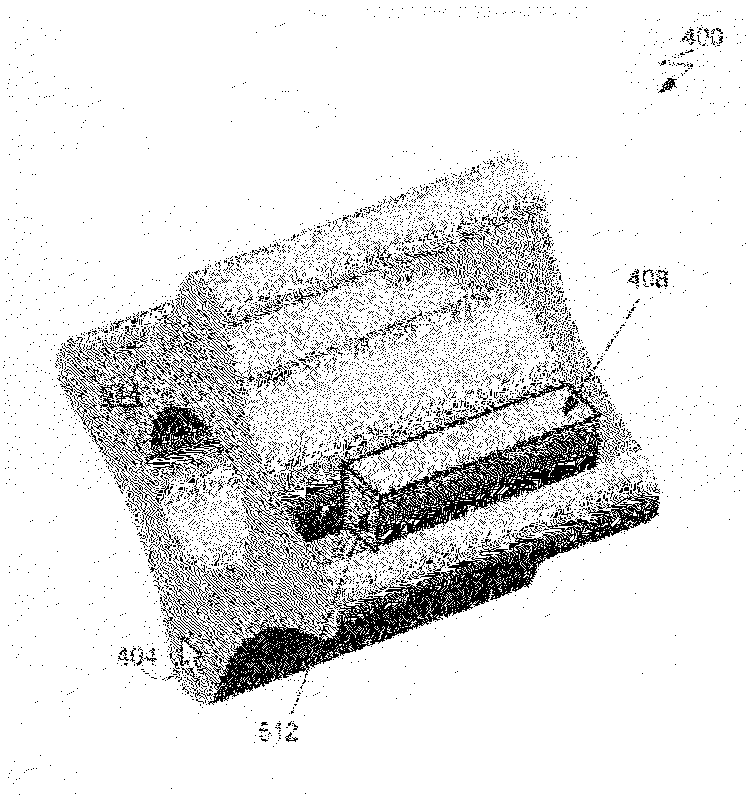
[0025]The present invention facilitates the selection of entities obscured by other entities displayed on a computer screen. A 3D CAD system that implements the present invention enables an engineer to temporarily hide obscuring entities, thus making other entities visible and easy to select using a commonly used selection technique to which he or she is accustomed.

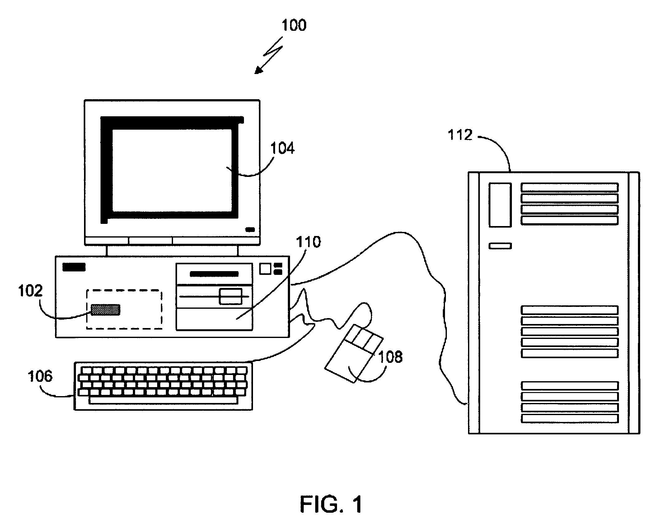
[0026]FIG. 1 shows a computerized modeling system 100 that includes a CPU 102, a CRT 104, a keyboard input device 106, a mouse input device 108, and a storage device 110. The CPU 102, CRT 104, keyboard 106, mouse 108, and storage device 110 can include commonly available computer hardware devices. For example, the CPU 102 can include a Pentium®-based processor. The mouse 108 may have conventional left and right buttons that the user may press to issue a command to a software program being executed by the CPU 102. As an alternative or in addition to the mouse 108, the computerized modeling system 100 can include a pointing...


PUM


Abstract

Selecting an obscured object of a computer-generated model consisting of a plurality of objects displayed on a computer screen includes receiving input data interpreted as an instruction to change a visibility characteristic of a first one of the plurality of objects (the first one of the objects obscuring another of the objects, and the first object being determined based on the location of an on-screen cursor), and modifying a visibility characteristic of the first object to cause another one of the objects to become discernable and selectable.

Description

BACKGROUND OF THE INVENTION[0001]Computer-aided design (CAD) software allows a user to construct and manipulate complex three-dimensional (3D) models of assembly designs. A number of different modeling techniques can be used to create a model of an assembly. These techniques include solid modeling, wire-frame modeling, and surface modeling. Solid modeling techniques provide for topological 3D models, where the 3D model is a collection of interconnected vertices, edges, and faces, for example. Geometrically, a 3D solid model is a collection of trimmed surfaces. The trimmed surfaces correspond to the topological faces bounded by the edges. Wire-frame modeling techniques, on the other hand, can be used to represent a model as a collection of simple 3D lines, whereas surface modeling can be used to represent a model as a collection of exterior surfaces. CAD systems may combine these and other modeling techniques, such as parametric modeling techniques. Parametric modeling techniques can...

Claims


Application Information

Patent Timeline
Patent Type & Authority Patents(United States)
IPC IPC(8): G06F3/00G06F9/44G06T15/40G06F3/033G06F17/50G06T15/00G06T19/00
CPCG06F17/50G06T19/00G06T2210/62G06F30/00
Inventor GIBSON, MARKWILKINSON, JAMES C.SWEENEY, JOHNMISRO, SEETHARAM
Owner DASSAULT SYST SOLIDWORKS CORP
Why Eureka
Try Eureka