Catalytic reactive component reduction system and methods for the use thereof

a reactive component and reduction system technology, applied in the direction of liquid-gas reaction process, chemical/physical process, propulsion parts, etc., can solve the problems of adding significantly to the cost of operation, and achieve the effect of reducing the venting of fuel-containing vapors

Active Publication Date: 2010-04-13
PHYRE TECH
View PDF3 Cites 73 Cited by
  • Summary
  • Abstract
  • Description
  • Claims
  • Application Information

AI Technical Summary

Benefits of technology

[0005]In accordance with the present invention, there are provided simplified systems and methods for catalytically reducing the concentration of one or more reactive component(s) in the vapor phase of fuel storage tanks. The simple apparatus described herein can be utilized to replace complex OBIGGS systems on the market. Simply stated, in one embodiment of the invention, the vapor phase from the fuel tank is passed over a catalytic bed operated at appropriate temperatures to allow the reaction between free oxygen and the fuel vapor by oxidation of the fuel vapor, thus deactivating reactive components in the gas phase. In addition, circulation and treatment of vapors as contemplated herein minimizes the venting of fuel-containing vapors to the atmosphere.
[0007]In yet another embodiment of the present invention, there are provided fuel storage systems for use in a vessel (e.g., an aircraft, a ship carrying flammable fluids as cargo, and the like), such fuel storage systems being capable of maintaining the concentration levels of one or more reactive components in the vapor phase of the fuel storage tank at sufficiently low levels so as to dramatically reduce the risk of fire and explosion therefrom. Moreover, circulation and treatment of vapors as contemplated herein minimizes the venting of fuel-containing vapors to the atmosphere.

Problems solved by technology

These, as well as other systems described in the prior art require elaborate setup and add significantly to the cost of operation based on the provision of an on board inert gas generator system (OBIGGS).

Method used


Image

  • Catalytic reactive component reduction system and methods for the use thereof
  • Catalytic reactive component reduction system and methods for the use thereof
  • Catalytic reactive component reduction system and methods for the use thereof

Examples


Embodiment Construction

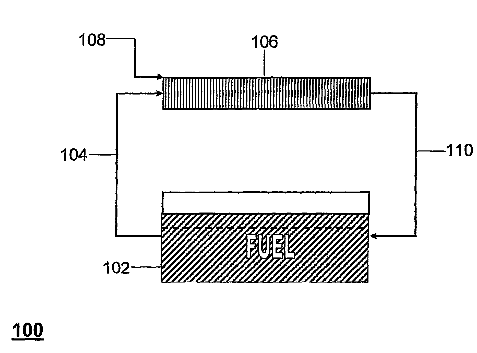
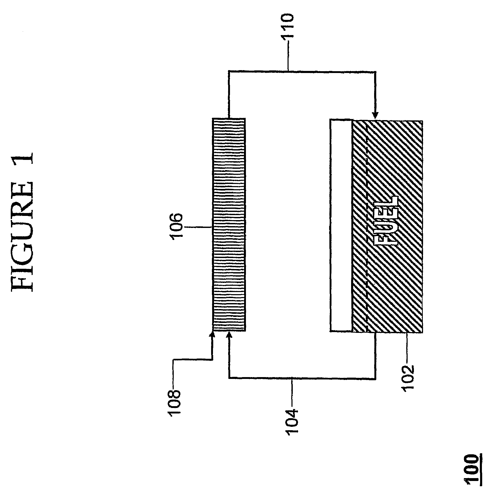
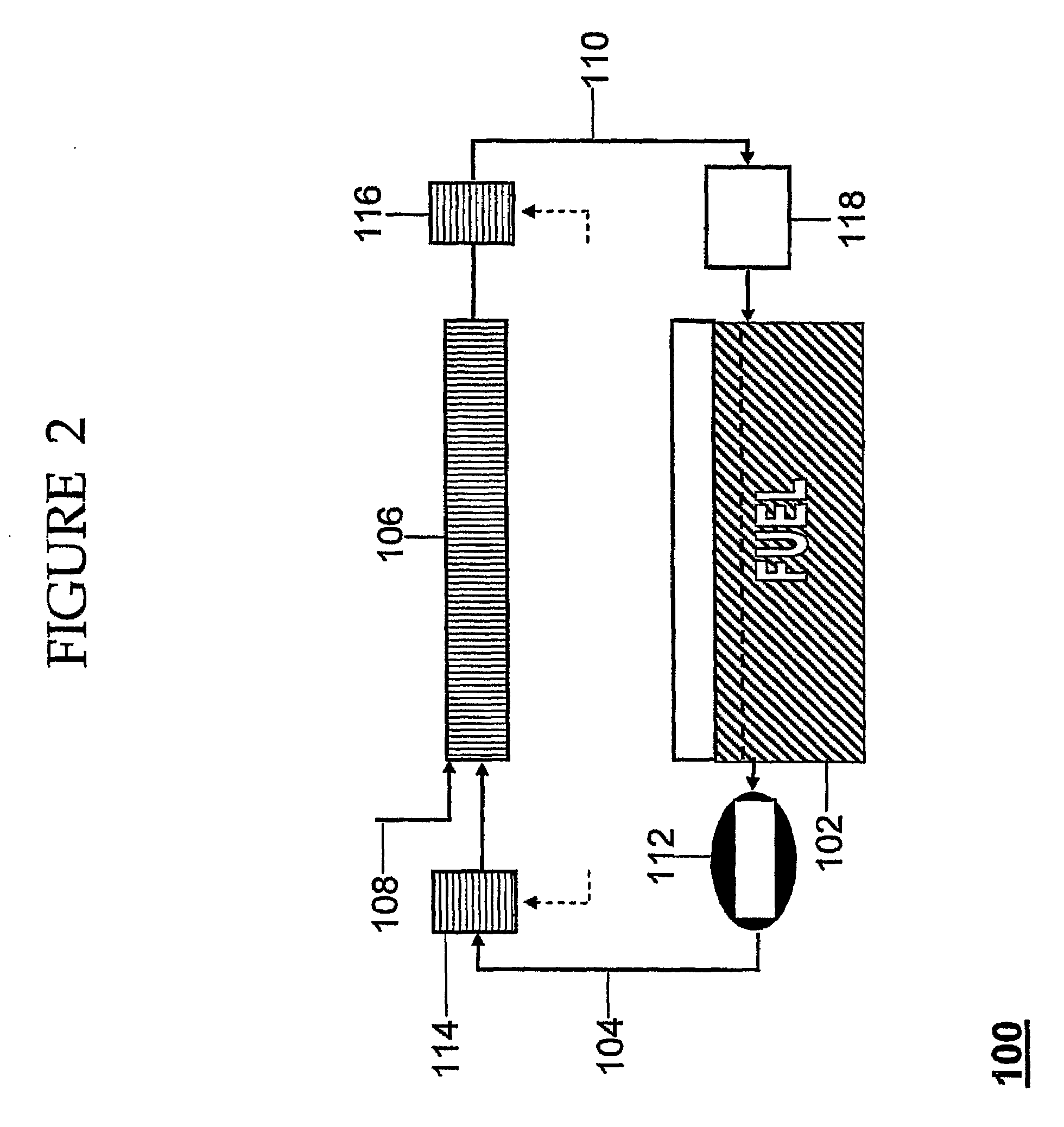
[0024]In accordance with the present invention, there are provided systems for reducing the concentration of one or more reactive component(s) from the vapor phase of a fuel storage tank (e.g., by deactivation of the reactive component(s) therein), wherein said fuel storage tank is provided with an outlet for removal of vapor therefrom and an inlet for return of vapor thereto. Invention systems comprise:[0025]a reaction zone, wherein said reaction zone provides conditions suitable to deactivate said one or more reactive component(s) when contacted therewith,[0026]an inlet to said reaction zone in fluid communication with the vapor space of said fuel storage tank via the outlet of the fuel storage tank, and[0027]an outlet from said reaction zone in fluid communication with the vapor space of said fuel storage tank via the inlet of the fuel storage tank.

[0028]As readily recognized by those of skill in the art, there are a variety of reactive components which one may desirably wish to ...


PUM

PropertyMeasurementUnit
temperatureaaaaaaaaaa
temperaturesaaaaaaaaaa

Abstract

In accordance with the present invention, there are provided simplified systems and methods for catalytically deactivating, removing, or reducing the levels of reactive component(s) from the vapor phase of fuel storage tanks. The simple apparatus described herein can be utilized to replace complex OBIGGS systems on the market. Simply stated, in one embodiment of the invention, the vapor phase from the fuel tank is passed over a catalytic bed operated at appropriate temperatures to allow the reaction between free oxygen and the fuel vapor by oxidation of the fuel vapor, thus deactivating reactive component(s) in the gas phase.

Description

FIELD OF THE INVENTION[0001]The present invention relates to the field of on board reactive component removal systems, and reaction systems and methods for the removal of reactive components from the vapor phase of fuel storage vessels. In a particular aspect, the invention relates to systems and methods for the catalytic removal of reactive components from the vapor phase of fuel storage vessels, specifically oxygen and / or fuel, thereby reducing the potential for fire and explosion in such vessels.BACKGROUND OF THE INVENTION[0002]In order to avoid the potential fire and explosion hazard in fuel tanks (e.g., aircraft fuel tanks, ships carrying flammable fluids as cargo, and the like), it is necessary to reduce the concentration of reactive components (e.g., oxygen and / or fuel vapors) in the gas phase that is in contact with liquid fuel. Many different approaches have been taken in efforts to address this problem. One such approach, for example, involves taking the bleed air from an ...

Claims


Application Information

Patent Timeline
Patent Type & Authority Patents(United States)
IPC IPC(8): B01J7/00B01J19/14B64D37/32
CPCB01D53/864B01D53/8671B64D37/32B01D2257/702B01D2257/104B60K15/03F02M33/02
Inventor LIMAYE, SANTOSHKOENIG, DONALD
Owner PHYRE TECH
Why Eureka
Try Eureka