

Reactive component reduction system and methods for the use thereof
a technology of reactive components and reduction systems, applied in chemical/physical processes, liquid-gas reaction processes, process and machine control, etc., can solve the problems of complex setup and significant cost of operation, and achieve the effect of reducing the risk of self-ignition and minimizing the venting of fuel-containing vapors
- Summary
- Abstract
- Description
- Claims
- Application Information
AI Technical Summary
Benefits of technology
Problems solved by technology
Method used
Image

Examples
Embodiment Construction
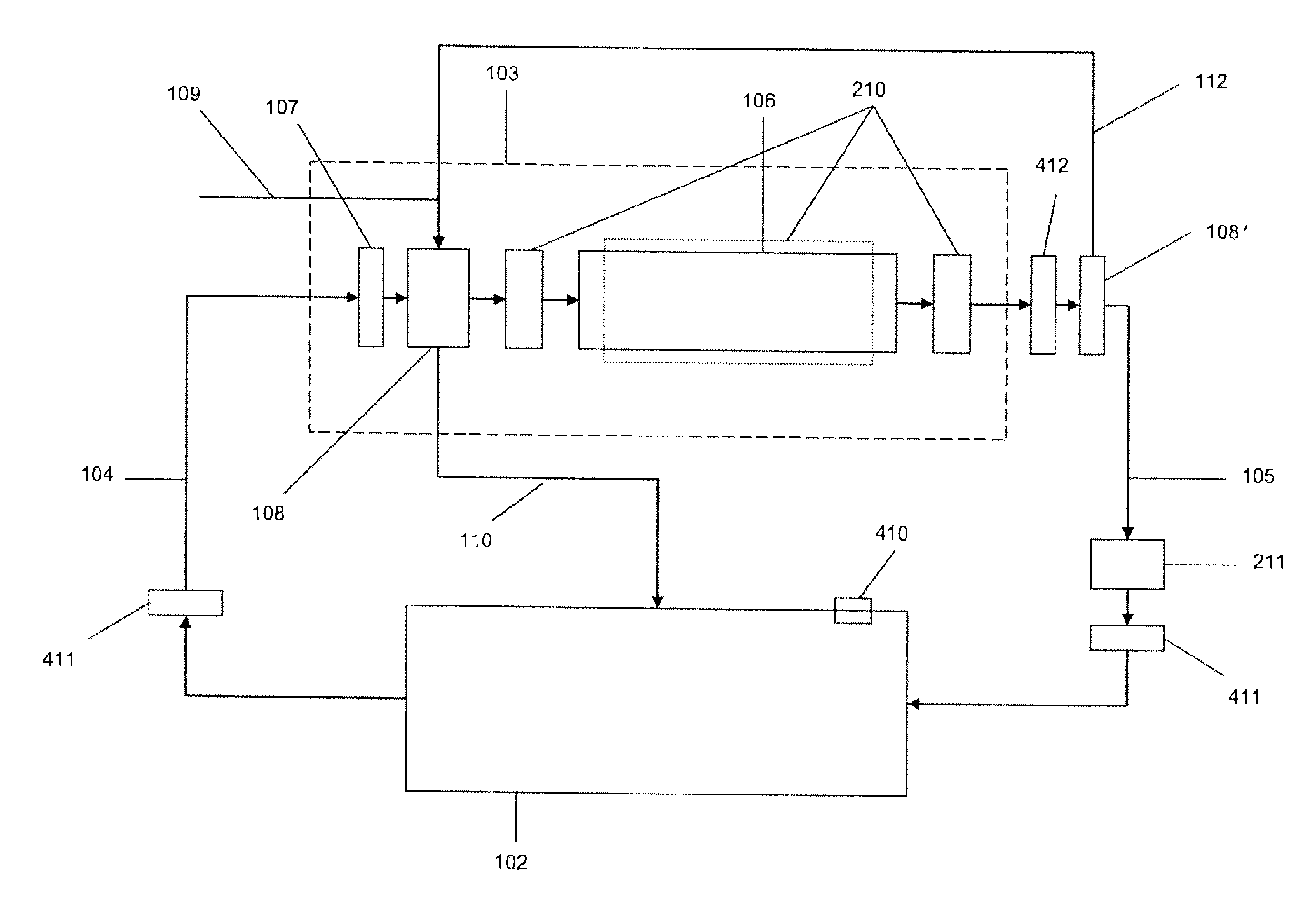
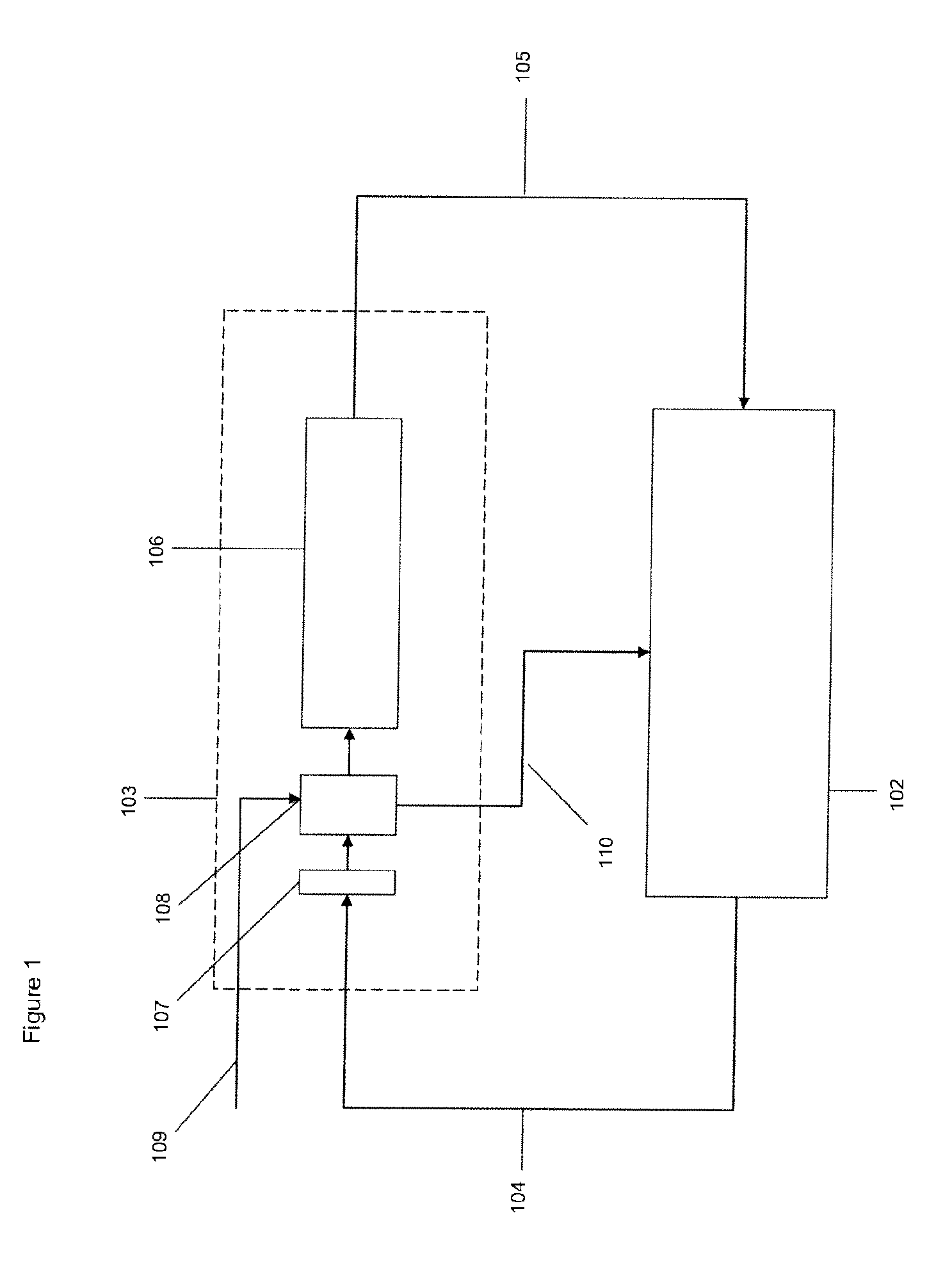
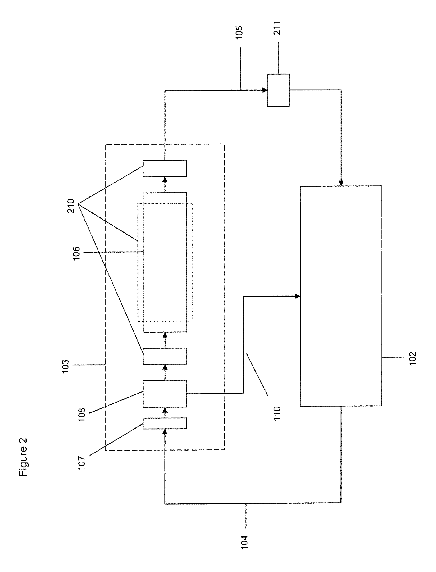
[0021]In accordance with the present invention, there are provided systems for reducing the concentration of one or more reactive component(s) in the vapor space of a container having combustible material therein, thereby reducing the concentration of reactive component(s) in said vapor space below the concentration at which auto-ignition may occur. Invention systems comprise:[0022]a storage container capable of storing combustible material therein,[0023]a fluid treating zone comprising:[0024]at least one inlet,[0025]at least one outlet, and[0026]a reaction zone, wherein said reaction zone provides conditions suitable to deactivate said one or more reactive component(s) when contacted therewith,[0027]at least one sensor for[0028](a) analysis of the concentration of reactive component(s) in the vapor phase,[0029](b) analysis of the concentration of combustible material in the vapor phase, and / or[0030](c) analysis of the flow rate of the vapor phase, and[0031]a flow control element,
wh...
PUM
| Property | Measurement | Unit |
|---|---|---|
| temperature | aaaaa | aaaaa |
| temperatures | aaaaa | aaaaa |
| temperatures | aaaaa | aaaaa |
Abstract
Description
Claims
Application Information