Device for detecting objects in a monitored area

a technology for detecting objects and monitored areas, applied in the direction of optical detection, burglar alarm short radiation actuation, instruments, etc., can solve the problem of low risk of confusing sensors, and achieve the effect of simple method of sensor parameterization

Active Publication Date: 2010-04-13
LEUZE ELECTRONICSLEUZE ELECTRONICS GMBH & CO KG
View PDF8 Cites 6 Cited by
  • Summary
  • Abstract
  • Description
  • Claims
  • Application Information

AI Technical Summary

Benefits of technology

[0009]It is thus an object of the present invention to provide a simple method of parameterization of sensors.
[0011]An advantage of the foregoing embodiment of the invention is that a fixed mechanical connection exists between a configuration module containing the stored configuration data and an installation or a machine. As a result, the machine-specific or installation-specific configuration data stored in the configuration module are fixedly assigned to the respective installation or the machine. Thus, during parameterization, i.e., during the configuration of sensors, there is a low risk of confusing the sensors. For performing parameterization, the sensor is connected directly to the machine or the installation, so that the configuration data can be transmitted from the configuration module to the sensor. As a result, configuring the sensor with incorrect configuration data intended for a different machine or the installation is consequently avoided with a high degree of certainty.
[0012]A further advantage of the foregoing embodiment of the invention is that a defective sensor can be replaced with a new sensor by simply removing the defective sensor from the configuration module and replacing it with the new sensor. The new sensor then takes over the configuration data from the configuration module, in the same way as the old sensor, thereby ensuring that the new sensor is configured identically to the old sensor. Also, as a result of the fixed mechanical connection between the configuration module and the machine or the installation, it is ensured that the new sensor is provided with the correct configuration data adapted to the machine or the installation.
[0014]The fixed mechanical connection between the configuration module and the respective machine or installation may be via a cable, wherein the configuration module is integrated into the cable itself or into a plug attached to the cable. Integrating the configuration module into a cable or a plug results in a particularly simple and space-saving arrangement of the configuration module.

Problems solved by technology

Thus, during parameterization, i.e., during the configuration of sensors, there is a low risk of confusing the sensors.

Method used


Image

  • Device for detecting objects in a monitored area
  • Device for detecting objects in a monitored area
  • Device for detecting objects in a monitored area

Examples


Embodiment Construction

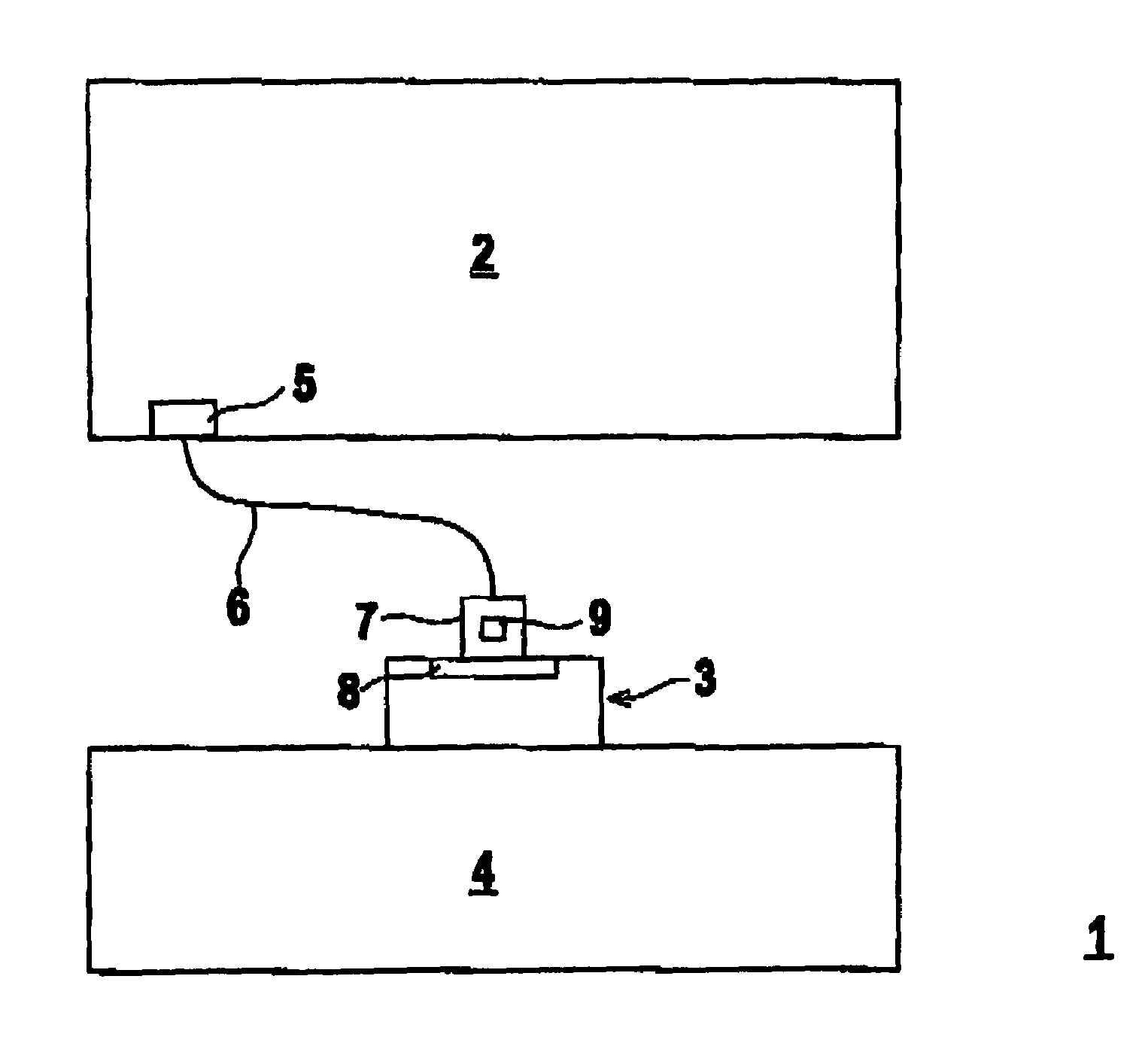
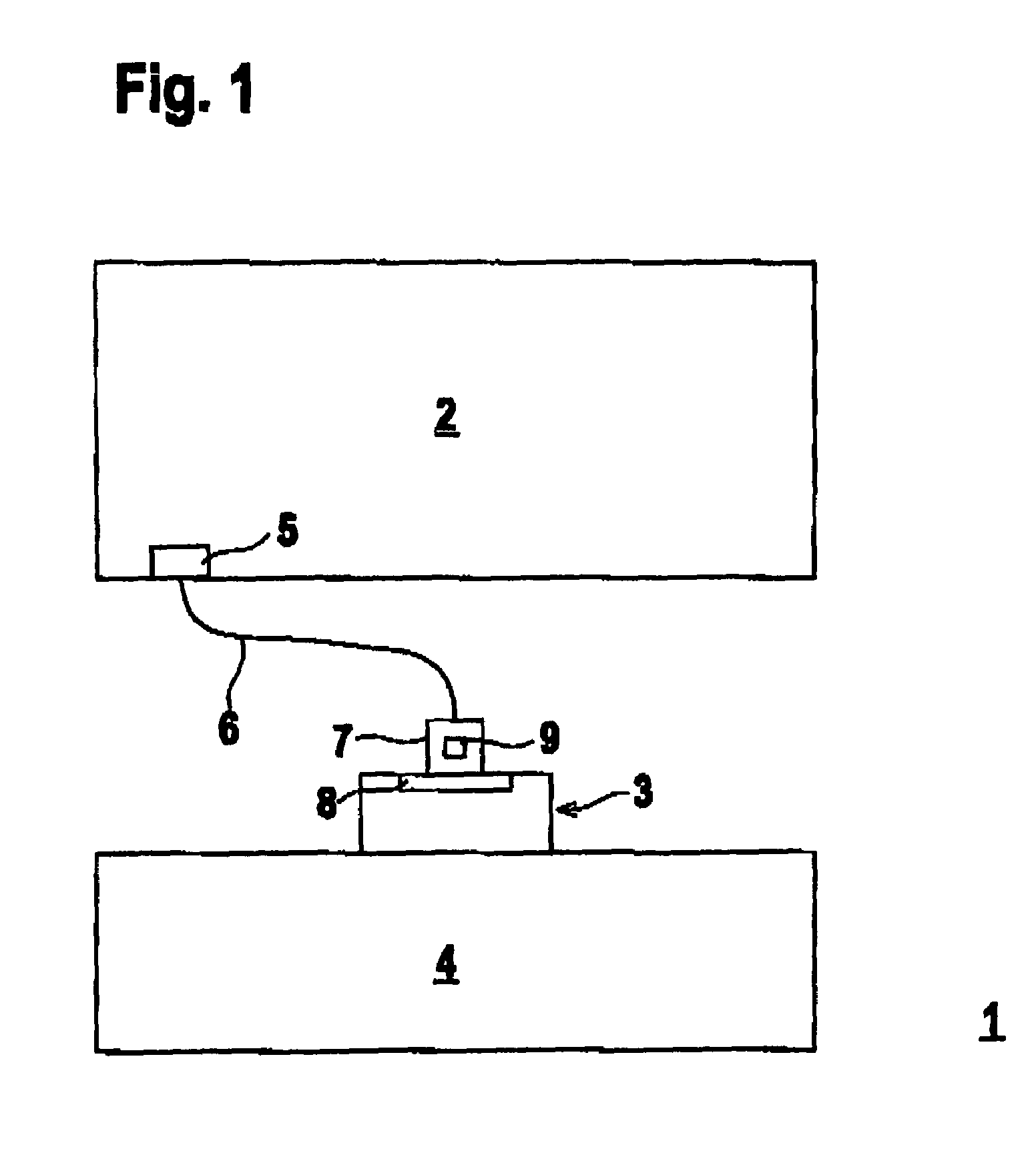
[0023]FIG. 1 shows a schematic view of an embodiment of the invention wherein a device 1 is used for securing a danger zone on a machine 2. The machine 2 may include a press or other devices that can be dangerous to personnel working within in a danger zone surrounding the machine 2. An optical sensor 3 is used to monitor a danger zone of the machine 2 to prevent danger to the personnel. To do so, the optical sensor 3 detects objects within a monitored area 4, the dimensions of which are adapted to the size of the danger zone. If the optical sensor 3 detects an object intervention within the monitored area 4, it generates a corresponding object detection signal, which functions as a control signal for the machine 2 and shuts down the machine 2 in order to avoid the danger.

[0024]The optical sensor 3 is linked to the machine 2 via a cable 6. The machine 2 is provided with a plug-and-socket connection 5 for connecting the cable 6. The free end of the cable 6 contains a plug 7 for conne...


PUM


Abstract

A device is provided for detecting an object within a monitored area of a machine or installation. The device includes at least one sensor for detecting objects within the monitored area. At least one configuration module is fixedly connected to the machine or the installation. The configuration module includes configuration data for the sensor, wherein the at least one configuration module feeds the sensor with the configuration data upon being connected to the sensor.

Description

CROSS-REFERENCE TO RELATED APPLICATION[0001]This application claims the priority of German Patent Application No: 10 2006 041 251.6, filed on Sep. 2, 2006, the subject matter of which is incorporated herein by reference.BACKGROUND[0002]1. Field of Invention[0003]The invention relates to a device for detecting objects inside a monitored area.[0004]2. Description of the Related Art[0005]When performing specific monitoring functions, for example monitoring objects or personnel near potentially dangerous machines or installations, objects are detected via a sensor that needs to be parameterized according to the specific machine or installation. In the event the sensor is defective and needs to be replaced with a new one, the new sensor needs to be provided with identical parameter values. In general, this not only requires a considerable amount of time, but also represents a source for errors. Carelessness of an operator in entering the parameter values for the new sensor may lead to sy...

Claims


Application Information

Patent Timeline
Patent Type & Authority Patents(United States)
IPC IPC(8): G06M7/00G08B13/18
CPCG01V8/10
Inventor LOHMANN, LUTZ
Owner LEUZE ELECTRONICSLEUZE ELECTRONICS GMBH & CO KG
Why Eureka
Try Eureka