Method for reading an image sensor

a technology of image sensor and image, applied in the field of image sensor reading, can solve the problems of inflexible use of line sensors, no line sensors available, and high technical effort in the implementation of machine vision systems

Active Publication Date: 2022-09-13
B&R IND AUTOMATION GMBH
View PDF12 Cites 0 Cited by
  • Summary
  • Abstract
  • Description
  • Claims
  • Application Information

AI Technical Summary

Benefits of technology

[0008]Embodiments of the present invention improve the prior art sensor solutions to provide higher flexibility and simpler application.
[0012]In an advantageous manner, the pixel range may comprise at least one complete sensor line. As a result, a single image sensor may render a plurality of linear sensors usable, each of which covers a specific linear area to be captured and has a specific angle of incidence. The parameterization is simplified as well.
[0014]In a further advantageous embodiment, the definition of the pixel range may be based on a predetermined parameterization. This facilitates, for example, the integration of the imaging device in an automation system which provides the parameters for the parameterization.
[0017]In a further advantageous embodiment, the definition of the pixel range may be changed dynamically. As a result, a “moving sensor position” may be realized without having to change the position of the imaging device. Optionally, moving objects may be “tracked” by the pixel range. This is done either by moving the image region that the pixel range is directed at on the object together with a fixed surface position or by having the image region “sweep over” a surface of the (moving or stationary) object to scan the surface of the object and, if necessary, create a corresponding image.
[0019]In a further advantageous embodiment of the invention, the definition of the pixel range for the imaging of a surface of an optionally moving object can be changed dynamically. This makes it possible, for example, to scan the surfaces of objects in a conveyor system for production errors without the object having to be brought into a special position or even stopped.
[0020]In a further aspect, embodiments of the present invention are directed to an imaging device of the type mentioned above which includes a pixel range encompassing at least one section of the image sensor defined by the control unit. The pixel range comprises at least a section of a sensor line and wherein the control unit limits the reading of the image sensor to the pixel elements in the pixel range. The imaging device facilitates an advantageous implementation of the method according to the invention.

Problems solved by technology

Numerous industrial applications require the use of complex optical sensor solutions, wherein in particular the implementation of machine vision systems is associated with a great deal of technical effort.
The use of line sensors is, however, somewhat inflexible and there are no line sensors available on the market that can be integrated into a central controller or drive system so that they can be synchronized with the movement of objects.
This raises the problem that the optimum angle must be determined and set manually.
On the one hand, this process is labor-intensive; on the other hand, it is difficult to reproduce and also error-prone.

Method used


Image

  • Method for reading an image sensor
  • Method for reading an image sensor
  • Method for reading an image sensor

Examples


Embodiment Construction

[0033]The particulars shown herein are by way of example and for purposes of illustrative discussion of the embodiments of the present invention only and are presented in the cause of providing what is believed to be the most useful and readily understood description of the principles and conceptual aspects of the present invention. In this regard, no attempt is made to show structural details of the present invention in more detail than is necessary for the fundamental understanding of the present invention, the description taken with the drawings making apparent to those skilled in the art how the several forms of the present invention may be embodied in practice.

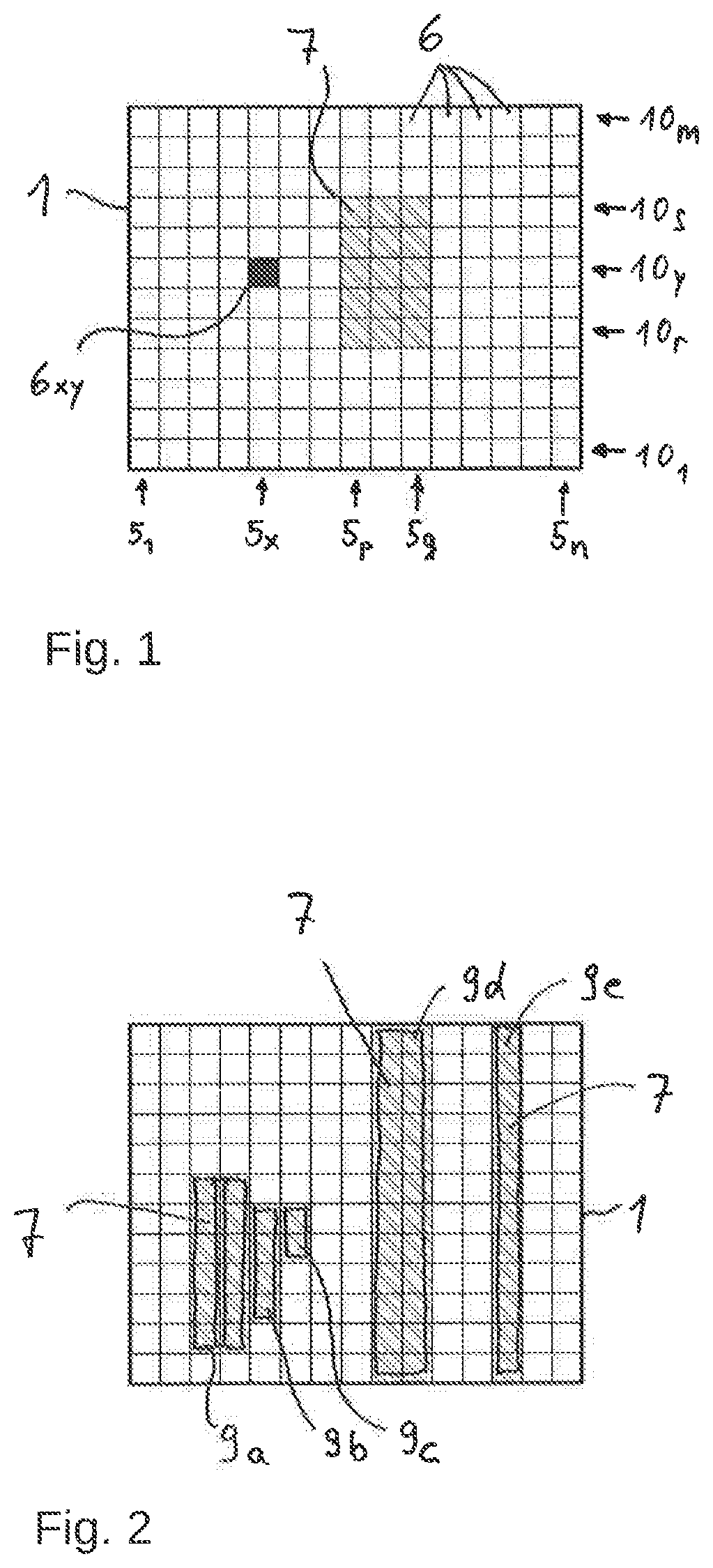
[0034]FIG. 1 shows a plan view of an image sensor 1 of an imaging device 2 (see FIG. 3) according to the invention in a highly schematic and simplified representation, which serves, in particular, to explain the designations and reference signs used herein. It basically shows the photosensitive, rectangular surface of the...


PUM

PropertyMeasurementUnit
lengthaaaaaaaaaa
rotational speedaaaaaaaaaa
shallow angleaaaaaaaaaa

Abstract

Imaging device and method for reading an image sensor in the imaging device. The imaging device has optics with which the imaging device can be focused on objects. The image sensor has a plurality of sensor lines, wherein each sensor line comprises a plurality of preferably linearly arranged, preferably individually readable pixel elements. A pixel range is defined with the pixel range comprising at least a section of a sensor line. The reading of the image sensor is restricted to the pixel elements (6) in the pixel range.

Description

CROSS-REFERENCE TO RELATED APPLICATIONS[0001]The present application claims priority under 35 U.S.C. § 119(a) of Europe Patent Application No. 18 20 8542.3 filed Nov. 27, 2018, the disclosure of which is expressly incorporated by reference herein in its entirety.BACKGROUND1. Field of the Invention[0002]The present invention relates to a method for reading an image sensor in an imaging device, wherein the imaging device has optics with which the imaging device can be focused on objects, wherein the image sensor has a plurality of sensor lines and wherein each sensor line comprises a plurality of preferably linearly arranged, preferably individually readable pixel elements. Furthermore, the invention relates to an imaging device having at least one image sensor, wherein the image sensor has a plurality of sensor lines and wherein each sensor line comprises a plurality of preferably linearly arranged, preferably individually readable pixel elements, optics with which the imaging device...

Claims


Application Information

Patent Timeline
Patent Type & Authority Patents(United States)
IPC IPC(8): G01N21/88H04N5/345
CPCG01N21/8851H04N5/3454H04N13/232G01B11/24G01N21/01G01N2021/0112H04N23/67H04N25/441H04N25/44H04N25/701H04N25/704H04N25/443
Inventor WALKNER, WALTERBEINHUNDNER, GERHARDWALDL, ANDREAS
Owner B&R IND AUTOMATION GMBH
Why Eureka
Try Eureka