Side-emitting lens for LED lamp

a technology of led lamps and side-emitting lenses, which is applied in the field of side-emitting lenses to achieve the effect of high degree of uniformity in the radial distribution

Active Publication Date: 2010-04-27
C R CONTROL SYST
View PDF16 Cites 72 Cited by
  • Summary
  • Abstract
  • Description
  • Claims
  • Application Information

AI Technical Summary

Benefits of technology

[0006]The present invention is for a side-emitting lens for use with an LED lamp. The lens of the present invention is well suited for fabrication by molding, and can provide a very high degree of uniformity in the radial distribution of the emitted light.

Problems solved by technology

The LED devices employed for providing the LED lamp typically do not provide a point source for generating light, but do generate light distributed about a centering point CP.

Method used


Image

  • Side-emitting lens for LED lamp
  • Side-emitting lens for LED lamp
  • Side-emitting lens for LED lamp

Examples


Embodiment Construction

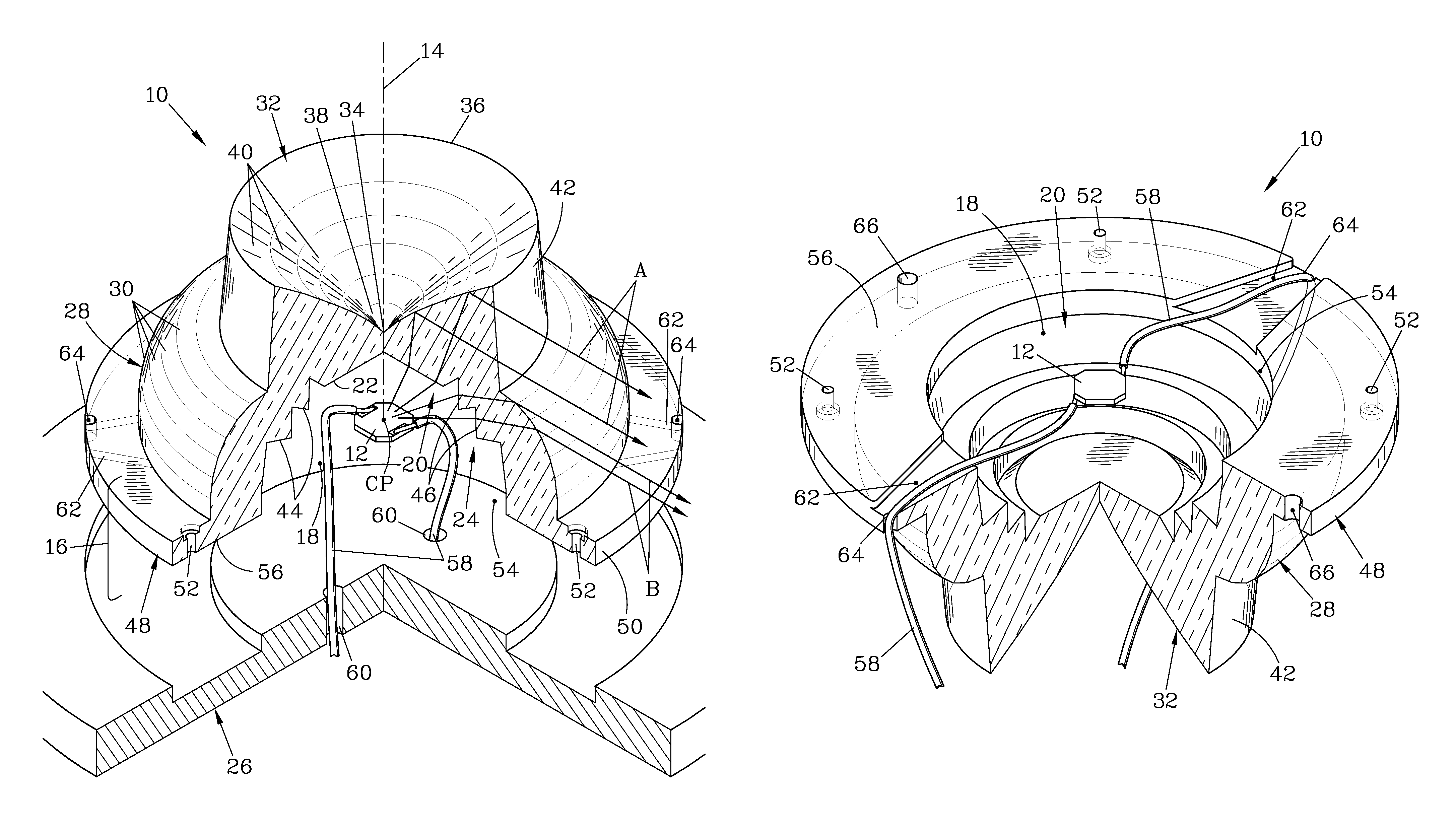
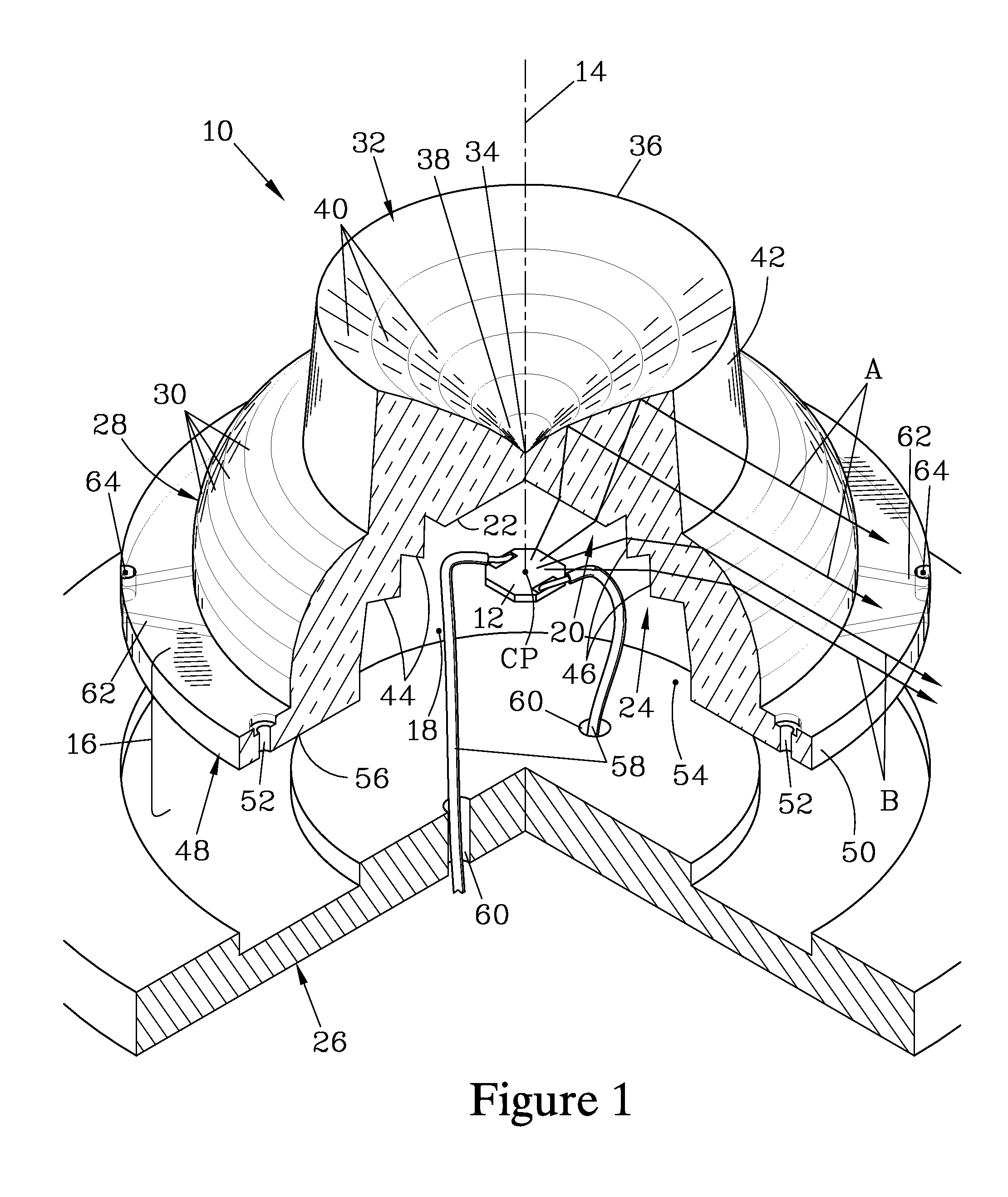
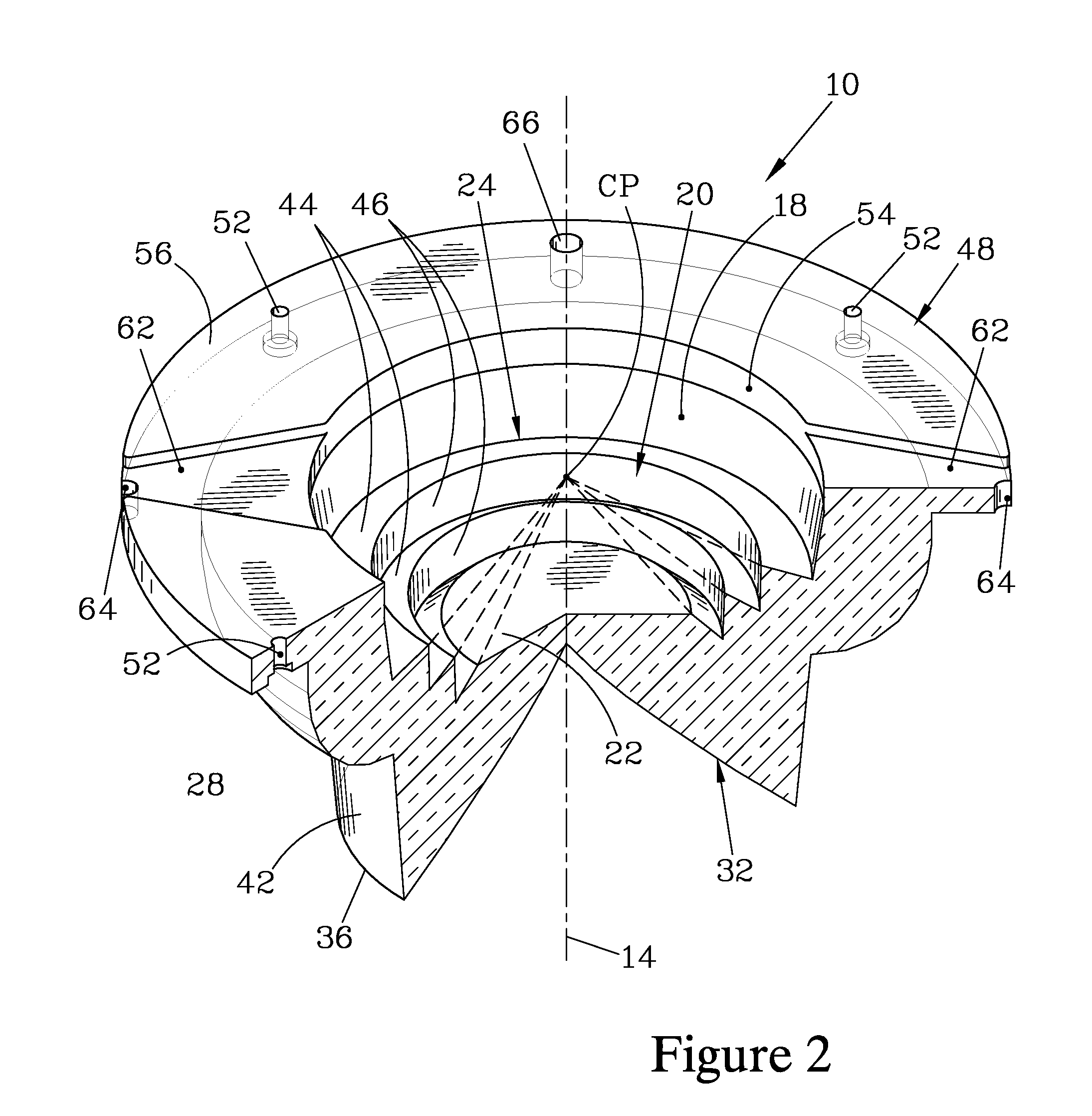
[0019]FIGS. 1-3 illustrate one embodiment of the present invention, a side-emitting lens 10 which serves to redirect light generated by an LED lamp 12. The lens 10 is symmetrically disposed about a central lens axis 14, and the lens 10 redirects the light from the LED lamp 12 in such a manner as to provide a distribution of emitted light which is substantially normal to the lens axis 14. Frequently, when the lens 10 is in service, it is oriented as illustrated with the central lens axis 14 substantially vertical; in such cases, the lens 10 will provide a distribution of emitted light which is substantially horizontal, making it well suited for use in marker luminaires used to mark buoys, fixed obstructions, and other objects of navigational importance.

[0020]The lens 10 has base section 16 which has a cavity 18 therein, which is symmetrically disposed about the central lens axis 14. The cavity 18 in turn is bounded by a cavity refracting surface 20 having a central section 22 that is...


PUM

PropertyMeasurementUnit
draft angleaaaaaaaaaa
widthaaaaaaaaaa
diameteraaaaaaaaaa

Abstract

A side-emitting lens for use with an LED lamp provides a distribution of emitted light that is substantially normal to an axis of symmetry of the lens; the light can also be symmetrical with respect to a plane normal to the lens axis. The lens has a cavity in which the LED lamp can reside, having a cavity refracting surface with a central section and a stepped cavity sidewall. The lens also has a base external refracting surface surrounding the cavity, an internal reflecting surface spaced apart from the cavity, and a side surface; these surfaces redirect light that enters the lens through the cavity refracting surface. For many applications, the lens axis is vertical in service and the lens is configured to provide a narrow distribution of light in the horizontal plane.

Description

FIELD OF THE INVENTION[0001]The present invention relates to side-emitting lenses that redirect the light emitted by a source such as an LED lamp to provide a distribution of light that is substantially symmetrical about an axis and is substantially normal thereto, and more particularly relates to such a lens that is particularly well suited for use in luminaires for marine applications marking buoys and similar objects.BACKGROUND OF THE INVENTION[0002]Luminaires which provide a generally horizontal distribution of emitted light have long been employed for marking objects of navigational interest, such as buoys and fixed obstructions. The horizontal distribution of light increases the efficiency of such luminaires, as it causes the light generated to be concentrated in the generally horizontal region where viewers are most likely to be located. This desired horizontal distribution has classically been attained by using cylindrical Fresnel lenses surrounding a centrally-located lamp,...

Claims


Application Information

Patent Timeline
Patent Type & Authority Patents(United States)
IPC IPC(8): F21V5/02
CPCB29C45/0025F21V23/002C03B11/08C03B11/082F21V5/04F21V5/046F21V7/0091G02B19/0071G02B19/0028G02B19/0061C03B2215/49F21W2111/04F21W2111/047F21Y2101/02H01L33/58B29C2045/0034F21Y2115/10
Inventor EWERT, JURGEN E.SEIDLER, JR., ROBERT L.
Owner C R CONTROL SYST
Why Eureka
Try Eureka