Suspension and sill system for sliding members

a sliding member and suspension system technology, applied in the direction of multi-purpose tools, wing accessories, manufacturing tools, etc., can solve the problems of difficult hanging of such members, inconvenient use of such panels, and inability to readily obtain skilled labor

Inactive Publication Date: 2010-05-11
EWING K BRADLEY
View PDF12 Cites 47 Cited by
  • Summary
  • Abstract
  • Description
  • Claims
  • Application Information

AI Technical Summary

Problems solved by technology

However, disadvantages in the use and installation of such panels are well known.
First, if the sliding members are heavy, hanging such members is difficult and two or more specialized installers may be required.
Second, continued and proper adjustment of the sliding panels is important for proper operation of the panels or doors and, again, skilled labor may not be readily available.
Third, existing sliding members generally have their entire weight acting on bearings located on the bottom of the door which run on a rail.
The rail is raised from the surface of the exterior and interior floors which causes access problems for carts and disabled users.
The debris may enter the bearings, prohibit smooth movement of the doors and cause premature wear.
In an effort to prevent this contamination, friction brushes are often used which, in turn, interfere with the smooth movement of the sliding members.
Fourth, the weight of such doors may act in an unbalanced way on the bearings if they are not precisely positioned.
Thus, one set of bearings may receive more loading than a second set of bearings which affects the operation of the doors and the bearing life.
This is unnecessarily expensive, time consuming and inconvenient for the user.

Method used


Image

  • Suspension and sill system for sliding members
  • Suspension and sill system for sliding members
  • Suspension and sill system for sliding members

Examples


Embodiment Construction

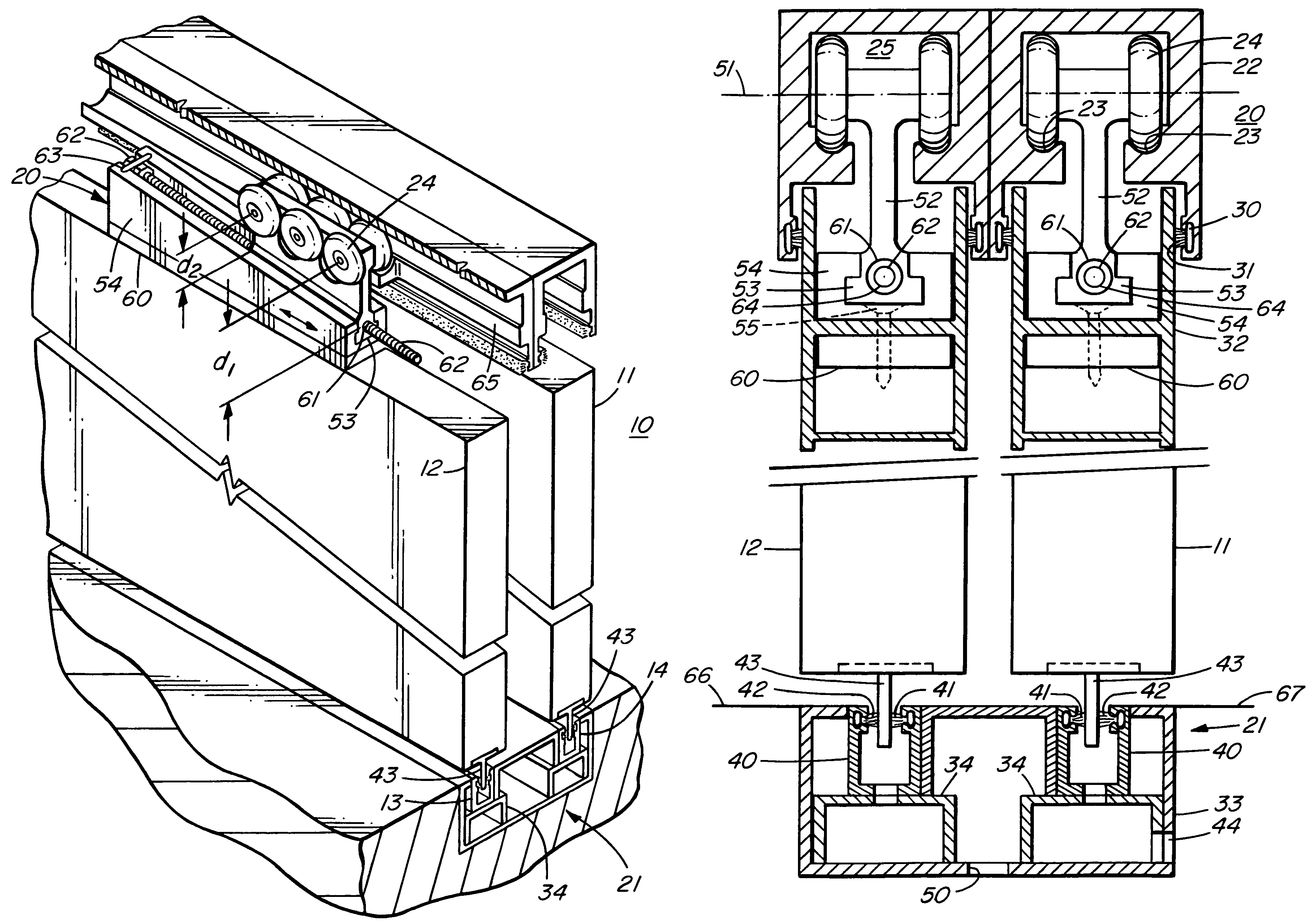
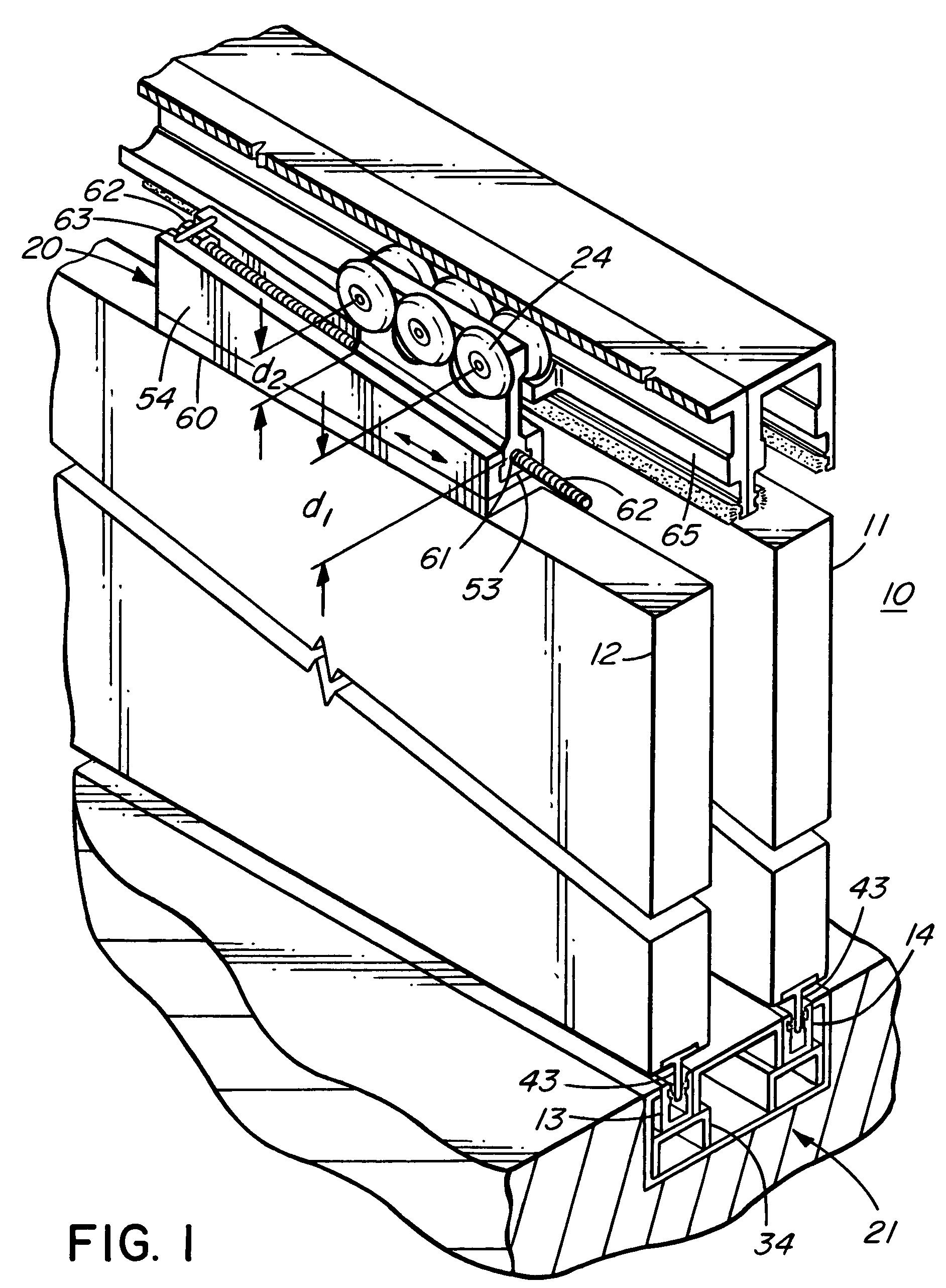
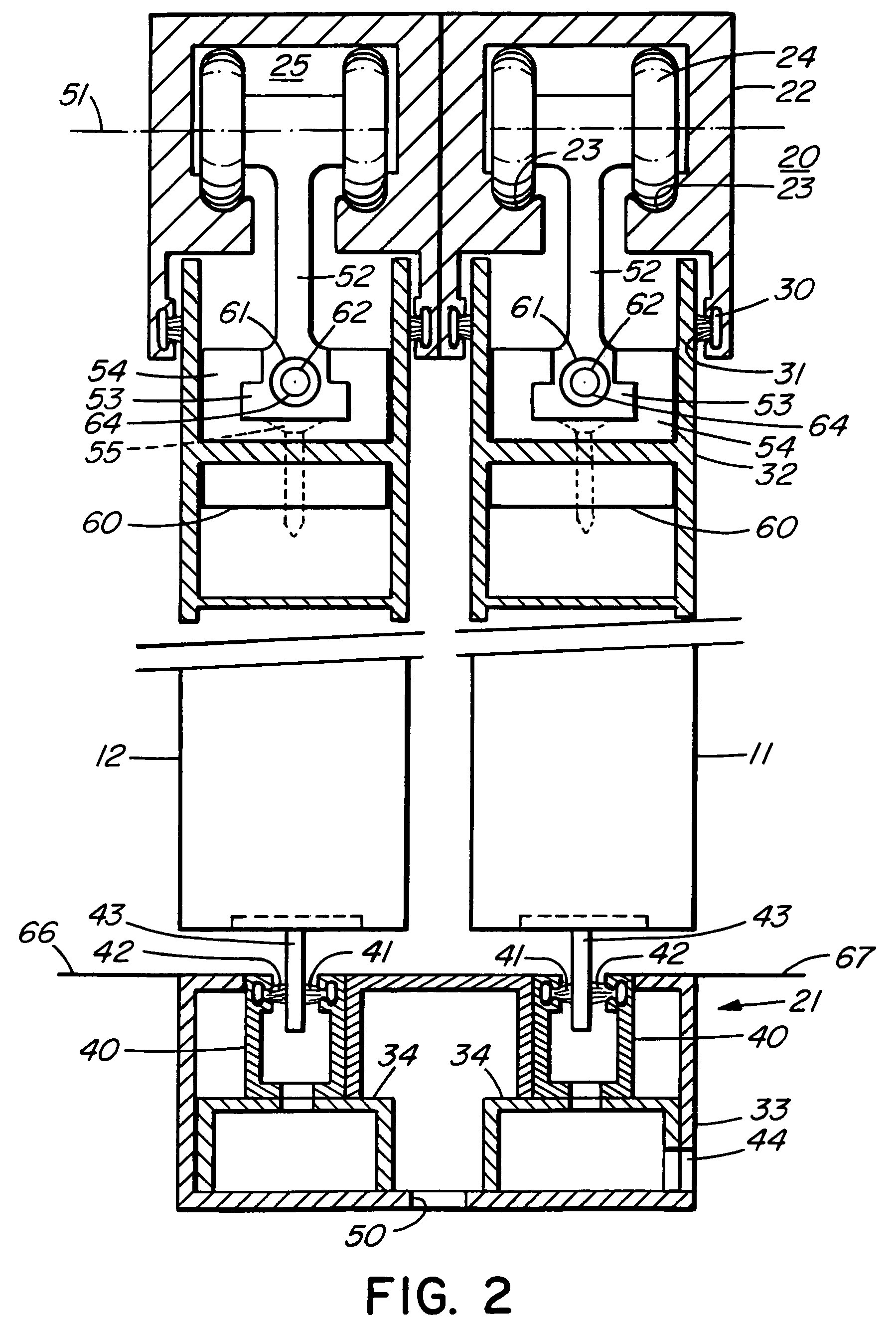
[0010]Referring now to the drawings, a set of sliding doors, in this case, two(2) such doors 11, 12 is generally shown at 10 in FIG. 1. The first and second doors 11, 12, respectively, move within respective guide strips 13, 14 and are each hung from a pair of upper hanging assemblies, one such hanging assembly being generally illustrated in detail at 20. A lower guide or sill assembly is generally illustrated at 21 in FIG. 2, it being understood that the upper hanging assemblies 20 and the lower guide or sill assembly 21 are the same for each of the sliding doors 11, 12.

[0011]A support bracket conveniently in the form of an aluminum extrusion 22 is mounted in the frame of the house or other structure (not shown). The support bracket 22 includes two(2) bearing guide paths 23 to allow the rotating bearings 24 of the bearing assembly 20 to move therein as will be described. The support bracket 22 also conveniently includes brush housings 30 which hold removable mohair brushes 31 used ...


PUM


Abstract

A panel or door suspension system used to hang sliding panels or doors. The panel members are hung by an upper bearing assembly with bearings on each side of the longitudinal axis of the panel thereby allowing the weight of the door to bear wholly on the upper bearings and to act centrally and downwardly between the bearings thereby preventing a moment on the bearings. A wedge member attached to the upper portion of the panel allows for vertical adjustment of the panel relative to the bearings and the door frame. A sill assembly beneath the panel allows for stable sliding operation of the panel member, provides for debris drainage and facilitates servicing of the members comprising the sill assembly.

Description

INTRODUCTION[0001]This invention relates to a suspension and sill system for sliding members and, more particularly, to a suspension and sill assembly system for heavy duty sliding doors or panels which doors or panels may be exposed to exterior weather conditions.BACKGROUND OF THE INVENTION[0002]Exterior sliding doors or panels which are opened and closed by sliding within a groove and which are maintained in their generally vertical position during the sliding movement are ubiquitous in residential and commercial construction. However, disadvantages in the use and installation of such panels are well known. First, if the sliding members are heavy, hanging such members is difficult and two or more specialized installers may be required. Second, continued and proper adjustment of the sliding panels is important for proper operation of the panels or doors and, again, skilled labor may not be readily available. Third, existing sliding members generally have their entire weight acting ...

Claims


Application Information

Patent Timeline
Patent Type & Authority Patents(United States)
IPC IPC(8): E05D13/00E05C7/06
CPCE05C7/06E05D15/0634E06B1/70E06B3/4636Y10T16/3834E05Y2900/132Y10T16/381
Inventor EWING, K. BRADLEYEWING, BRENT JOHNHEWSON, BRUCE
Owner EWING K BRADLEY
Why Eureka
Try Eureka