Supporting device

a support device and support plate technology, applied in the direction of sheet joining, screws, dynamo-electric machines, etc., can solve the problems of many anchors on the market that are instable, difficult to install, and cannot meet the needs of heavy loads

Active Publication Date: 2010-05-11
ANNE MARIE SEDGWICK +1
View PDF98 Cites 61 Cited by
  • Summary
  • Abstract
  • Description
  • Claims
  • Application Information

AI Technical Summary

Problems solved by technology

Anchors have become increasingly popular for mounting objects where screws, nails, adhesives or other simple fasteners are either impractical or ineffective.
A problem with anchors is that they are difficult to install, which is particularly problematic for individuals who do not have the skills or tools for performing difficult installations.
Moreover, many anchors on the market are instable and do not adequately support heavy loads, especially in dry wall.
In addition, they may also loosen over time, causing damage to the support structure on which they are mounted.

Method used


Image

  • Supporting device
  • Supporting device
  • Supporting device

Examples


Embodiment Construction

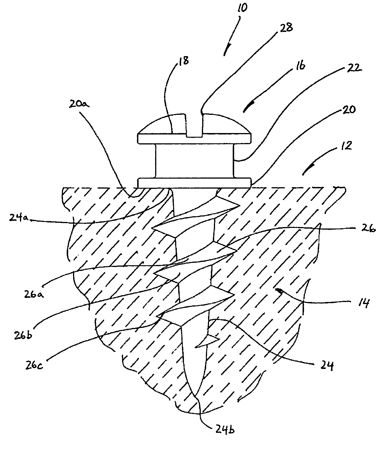
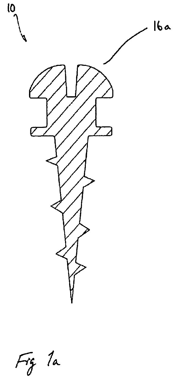
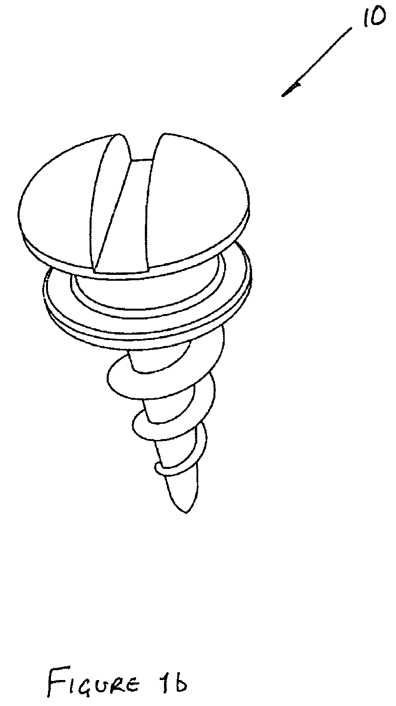
[0037]Referring to the figures, particularly FIGS. 1a to 1c, there is shown a support device 10 for supporting an article (such as, for example, a picture frame, not shown) on a structure, for example a wall 12. The support device 10 has an elongate one piece body 14 having a support head portion 16 located at one end thereof. The support head portion 16 includes a head 18 and a shoulder flange 20 which are separated by a neck 22.

[0038]As will be described, the head 18 and / or neck 22 are arranged to engage the article while the shoulder flange 20 has a surface 20a for engaging a corresponding surface of the structure.

[0039]The elongate body 14 has an elongate shank portion 24 for anchoring the support device at a target site on the structure. The elongate shank portion is, in this example, screw threaded with a proximal end 24a adjacent the shoulder flange 20 and a distal end 24b, and the shank portion 24 decreases in cross-section from the proximal end to the distal end 24b.

[0040]...


PUM


Abstract

A device for supporting an article on a structure. The support device includes an elongate body with a head at one end, a neck, a shoulder flange, and an elongate threaded shank with threads extending therefrom. The head and / or neck may be arranged to engage the article, and the shoulder flange has a surface for engaging a corresponding surface of the structure. The elongate shank portion anchors the support device at a target site on the structure and tapers from a greatest diameter proximate to the shoulder flange to a pointed end. The initial taper is at a lesser angle to the longitudinal axis of the elongate body to a point where the angle increases, before which the threads may terminate.

Description

REFERENCE TO CO-PENDING APPLICATIONS[0001]The entire subject matter of U.S. Provisional application Ser. No. 60 / 626,776 filed Nov. 10, 2004 and entitled SUPPORTING DEVICE is incorporated by reference. The applicant claims priority benefit under Title 35, United States Code, Section 119(e) of U.S. Provisional application Ser. No. 60 / 626,776 filed Nov. 10, 2004 and entitled SUPPORTING DEVICE[0002]The applicant claims priority benefit under Title 35, United States Code, Section 119 of Canadian application serial number 2,484,381 filed Oct. 8, 2004 and entitled SUPPORTING DEVICE.TECHNICAL FIELD[0003]The invention relates to a supporting device and is especially applicable to a supporting device for supporting an article from a support structure.BACKGROUND ART[0004]Anchors have become increasingly popular for mounting objects where screws, nails, adhesives or other simple fasteners are either impractical or ineffective.[0005]A problem with anchors is that they are difficult to install, w...

Claims


Application Information

Patent Timeline
Patent Type & Authority Patents(United States)
IPC IPC(8): F16B35/04
CPCA47G1/20F16B35/06F16B35/048F16B23/0092F16B23/0007F16B25/00
Inventor SEDGWICK, LEONARD JOHNSEDGWICK, ANNE MARIE
Owner ANNE MARIE SEDGWICK
Why Eureka
Try Eureka