Position indicating and guidance system and method thereof

a technology of positioning indication and guidance system, applied in the direction of direction/deviation determining electromagnetic system, angle measurement, instruments, etc., can solve the problems of prone to human error, require highly skilled operators, and standard surveying techniques are relatively slow, so as to eliminate the time-consuming tilting and plane alignment

Active Publication Date: 2010-05-11
TRIMBLE NAVIGATION LTD
View PDF9 Cites 3 Cited by
  • Summary
  • Abstract
  • Description
  • Claims
  • Application Information

AI Technical Summary

Benefits of technology

[0007]It is against the above background, that the present invention provides a position indicating and guidance system providing at least depth and line information of a tool carried by a machine, such as for example, a scoop of an excavator or backhoe, or a bucket of a loader using a single laser transmitter and a receiver having a photodetector array. In one embodiment, the receiver provides integral grade and line indicators. Grade is simply set by entering it in the receiver, thereby eliminating the time consuming tilting and plane alignment required with conventional systems. In another embodiment, six degrees of positional information (x, y, z, pitch, roll, and yaw) is also provided by receiver from sensing the reference fans from the laser transmitter.
[0008]The present invention also provides the benefit of giving machine operators the ability to follow a predetermined path and achieve desired digging depth by watching steering and elevation indicators also provided to the receiver. The indicators of the position indicating system are activated by data derived from interception of signals generated by a single laser transmitter by the photodetector array. It is to be appreciated that because a photodetector array is used, the present invention provides the added benefit of increasing the vertical receiving range to meters, as opposed to the typical ±2 to 4 inches of vertical receiving range of a conventional laser receiver. As such, the present invention substantially reduces or eliminates the time need to deploy stakes and string lines, sync with the laser transmitter (i.e., beam searching), and the cost associated with using a second laser transmitter.
[0009]In one embodiment, a method for guiding a machine carrying a tool for movement along a predetermined path at a worksite is disclosed. The method comprises placing a fan-type laser transmitter at the worksite remote from the machine. The laser transmitter has an arbitrary reference direction and generates two fan-shaped laser beams. The method also includes sensing the two fan-shaped beams with at least four photodetectors fixed arbitrarily at known positions in a detector array having a three-dimensional shape. The detector array is placed at a known position on the machine. The method further includes setting a reference azimuth angle from the arbitrary reference direction into a control unit provided on the machine, the reference azimuth angle points in a direction parallel to the predetermined path, and computing a measured azimuth angle using information provided to the control unit by the detector array sensing the two fan-shaped beams. Additionally, the method includes determining position of the machine relative to the predetermined path via the control unit comparing the measured azimuth angle to the reference azimuth angle, and generating signals which help guide the machine along the predetermined path.

Problems solved by technology

Standard surveying techniques are relatively slow, require highly skilled operators, and remain prone to human error.
Accordingly, the available data is limited to elevation over a rather small vertical range, and thus due to plane tilting and alignment iteration, establishing grade with such a conventional laser system is time consuming.
However, in both the former and latter systems, information regarding the relative distance and direction (azimuth) from the receiver to the transmitter is not established.
These narrow limits often result in the operator “searching for the beam” to regain depth indication.
However, these methods have known drawbacks.
Line destruction resulting from construction site activity may result in digging delays, and using an additional laser is expensive.
Accordingly, establishing distance, direction, and grade using a conventional laser system, stakes, string lines, pipe lasers, or a second transmitter is time consuming and adds additional costs.

Method used


Image

  • Position indicating and guidance system and method thereof
  • Position indicating and guidance system and method thereof
  • Position indicating and guidance system and method thereof

Examples


Embodiment Construction

[0018]While the invention may be susceptible to embodiment in different forms, there is shown in the drawings, and herein will be described in detail, specific embodiments with the understanding that the present disclosure is to be considered an exemplification of the principles of the invention, and is not intended to limit the invention to that as illustrated and described herein.

[0019]Skilled artisans appreciate that elements in the drawing are illustrated for simplicity and clarity and have not necessarily been drawn to scale. For example, the dimensions of some of the elements in the drawing may be exaggerated relative to other elements to help to improve understanding of the various embodiments of the present invention.

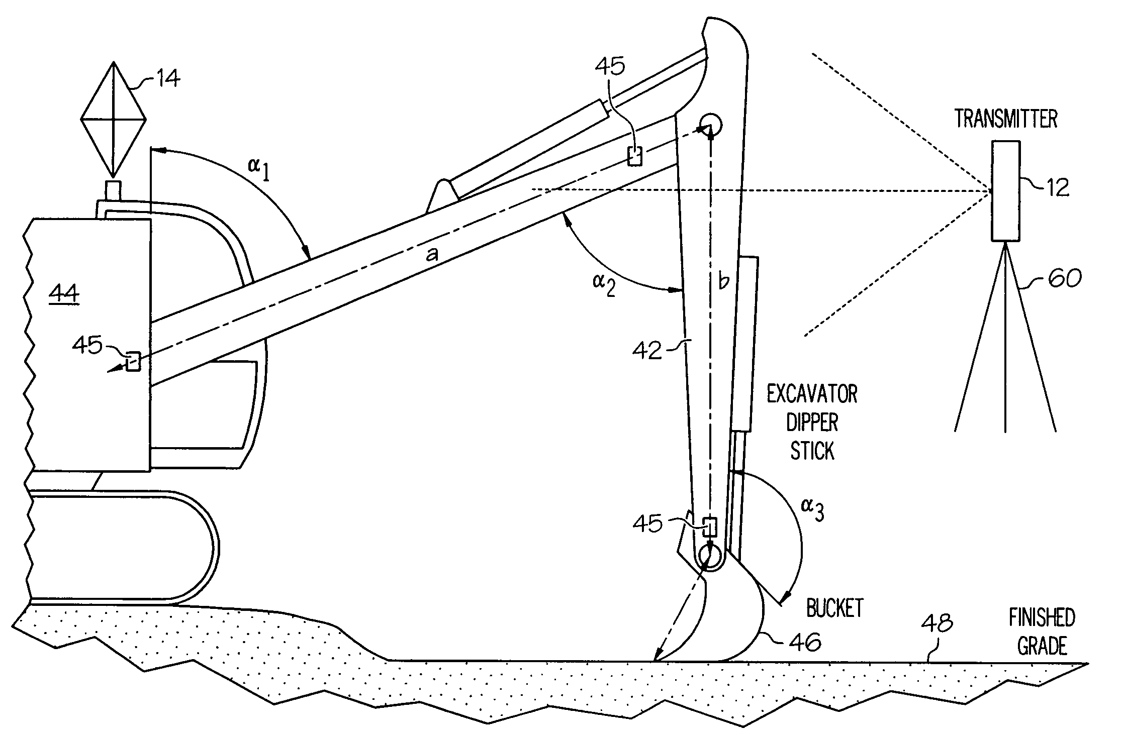
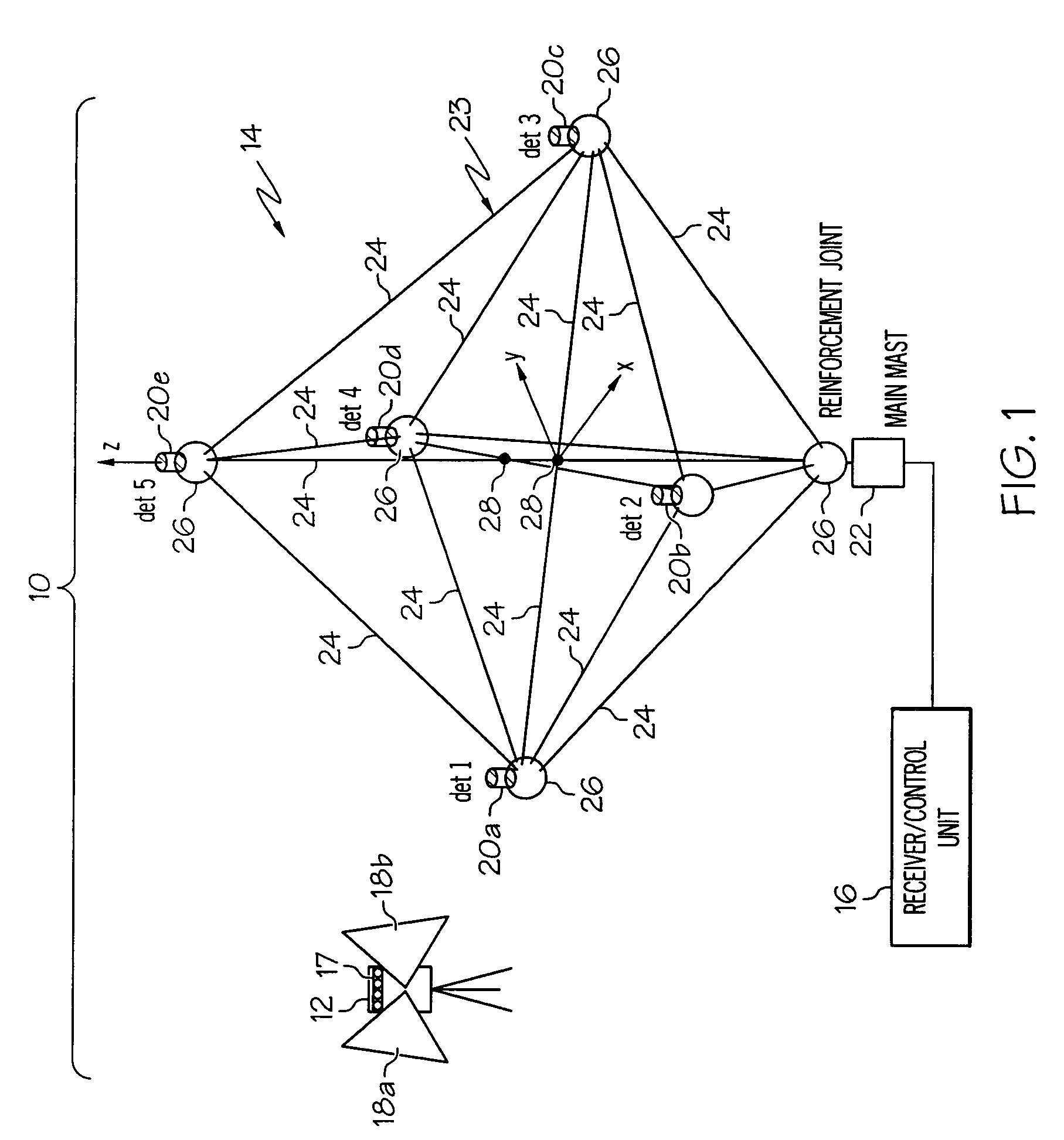
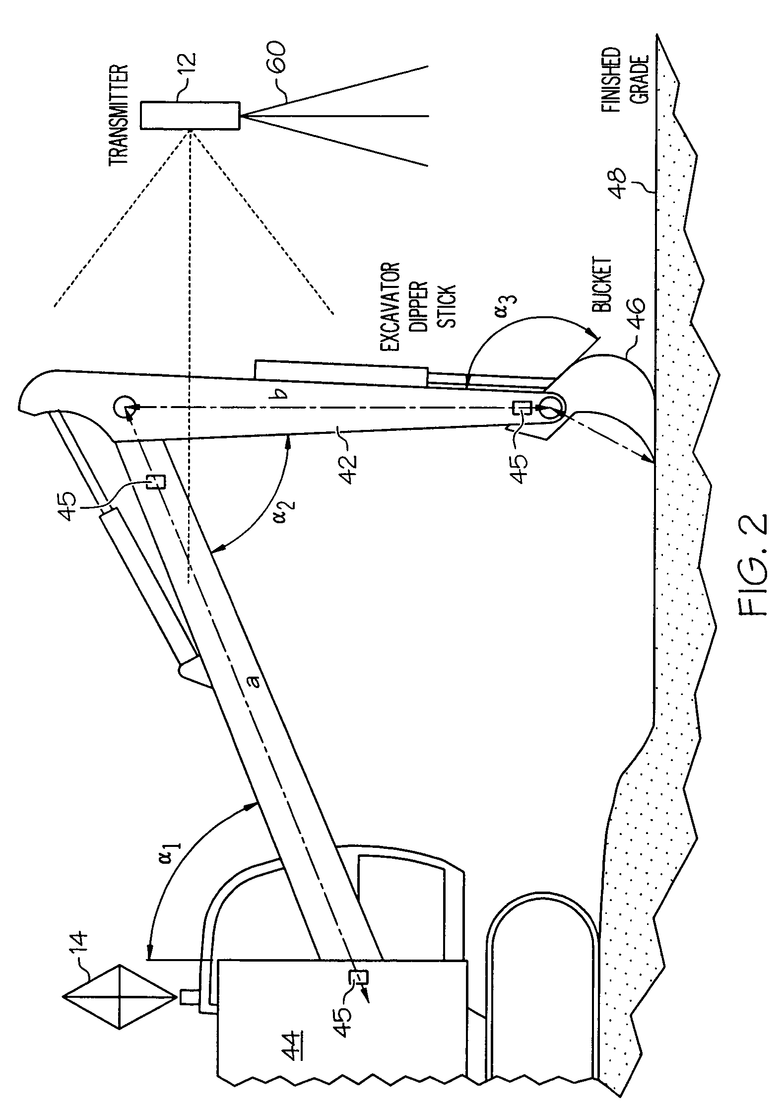
[0020]FIG. 1 shows generally one illustrative embodiment of a position indication system 10 according to the present invention. The present invention addresses all the problems mentioned in the background above by providing a single fan-type laser transmitter 12...


PUM


Abstract

The present invention provides operators the ability to follow a predetermined path and achieve desired digging depth by watching steering and elevation indicators of just one system. The indicators are activated by data derived from the interception of signals generated by a single laser transmitter and a receiver array mounted on the machine. The system according to the present invention uses the multiple, tilted fan beams provided by the laser transmitter to calculate elevation angle and azimuth of the tool carried by machine.

Description

BACKGROUND OF THE INVENTION[0001]The present invention relates generally to position indicating and guidance systems and in particular, to a control system and method providing positional and guidance information to a machine carrying a tool for movement along a predetermined path at a worksite using a single laser transmitter and a detector array.[0002]Construction relies heavily on positioning data. Construction performance, in particular productivity and quality of work, is tied to the speed and accuracy of positioning methods being used. Standard surveying techniques are relatively slow, require highly skilled operators, and remain prone to human error.[0003]In a prior art laser transmitter, a narrowly focused, horizontally rotating beam of laser energy is used to provide a reference plane. The rotating beam intercepts a vertically extending array of photodetectors in a laser receiver to mark the elevation of the receiver with respect to the laser beam. The array extends typical...

Claims


Application Information

Patent Timeline
Patent Type & Authority Patents(United States)
IPC IPC(8): G01C1/00
CPCE02F3/437E02F9/26G01S3/784G01C15/002G01S1/70
Inventor CAIN, GARYNICHOLS, MARKTAKAGI, HIROYUKI
Owner TRIMBLE NAVIGATION LTD
Why Eureka
Try Eureka