Tire pressure gauge with cap wrench

a technology of pressure gauge and wrench, which is applied in the field of pressure gauge, can solve the problems of difficult removal of tire valve caps and the amount of force required to remove caps

Inactive Publication Date: 2010-05-25
MEASUREMENT
View PDF88 Cites 10 Cited by
  • Summary
  • Abstract
  • Description
  • Claims
  • Application Information

AI Technical Summary

Problems solved by technology

Sometimes, tire valve caps may be difficult to remove because dirt may be lodged between the valve stem and the cap.
Under such circumstances, some amount of force may be required to remove the cap.

Method used


Image

  • Tire pressure gauge with cap wrench
  • Tire pressure gauge with cap wrench
  • Tire pressure gauge with cap wrench

Examples


Embodiment Construction

[0016]It is to be understood that the figures and descriptions of the present invention have been simplified to illustrate elements that are relevant for a clear understanding of the present invention, while eliminating, for purposes of clarity, many other elements found in pressure gauges. However, because such elements are well known in the art, and because they do not facilitate a better understanding of the present invention, a discussion of such elements is not provided herein. The disclosure herein is directed to all such variations and modifications known to those skilled in the art.

[0017]Further, it should be understood that the several views of the housings, displays and general configurations shown in the figures include many decorative or ornamental features, aspects of which the particulars may be changed while maintaining the device's utility and without departing from the scope and spirit of the present invention.

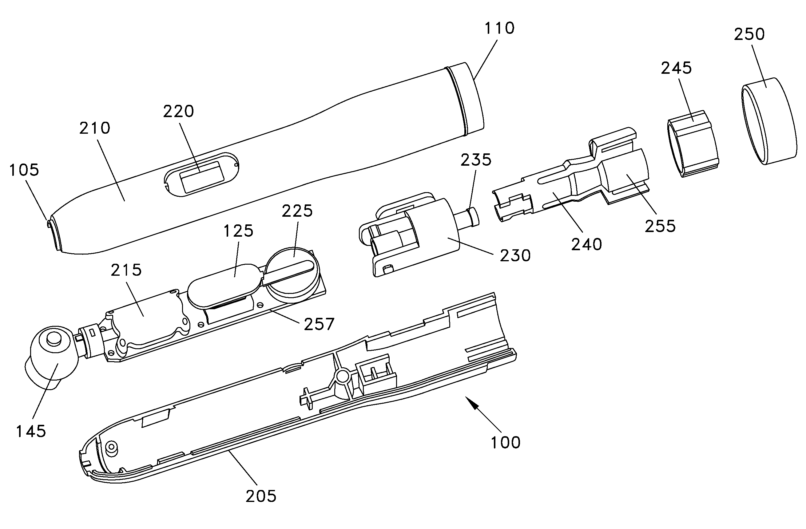
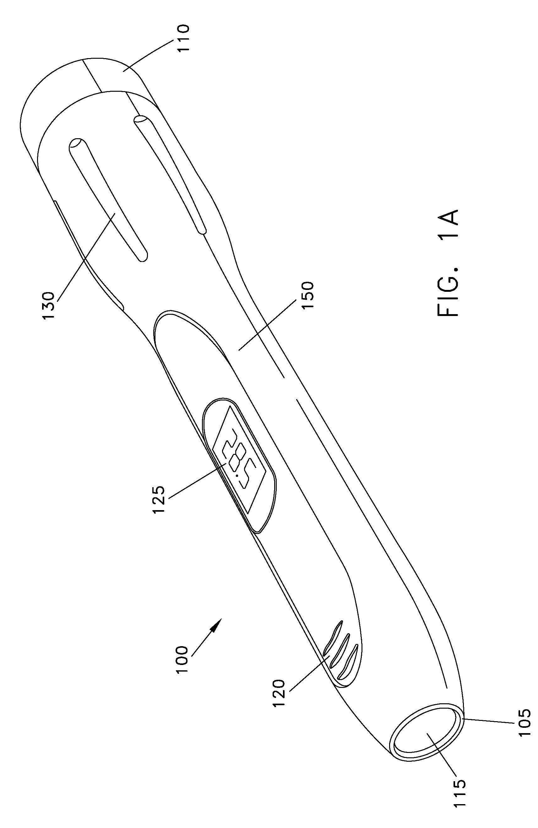
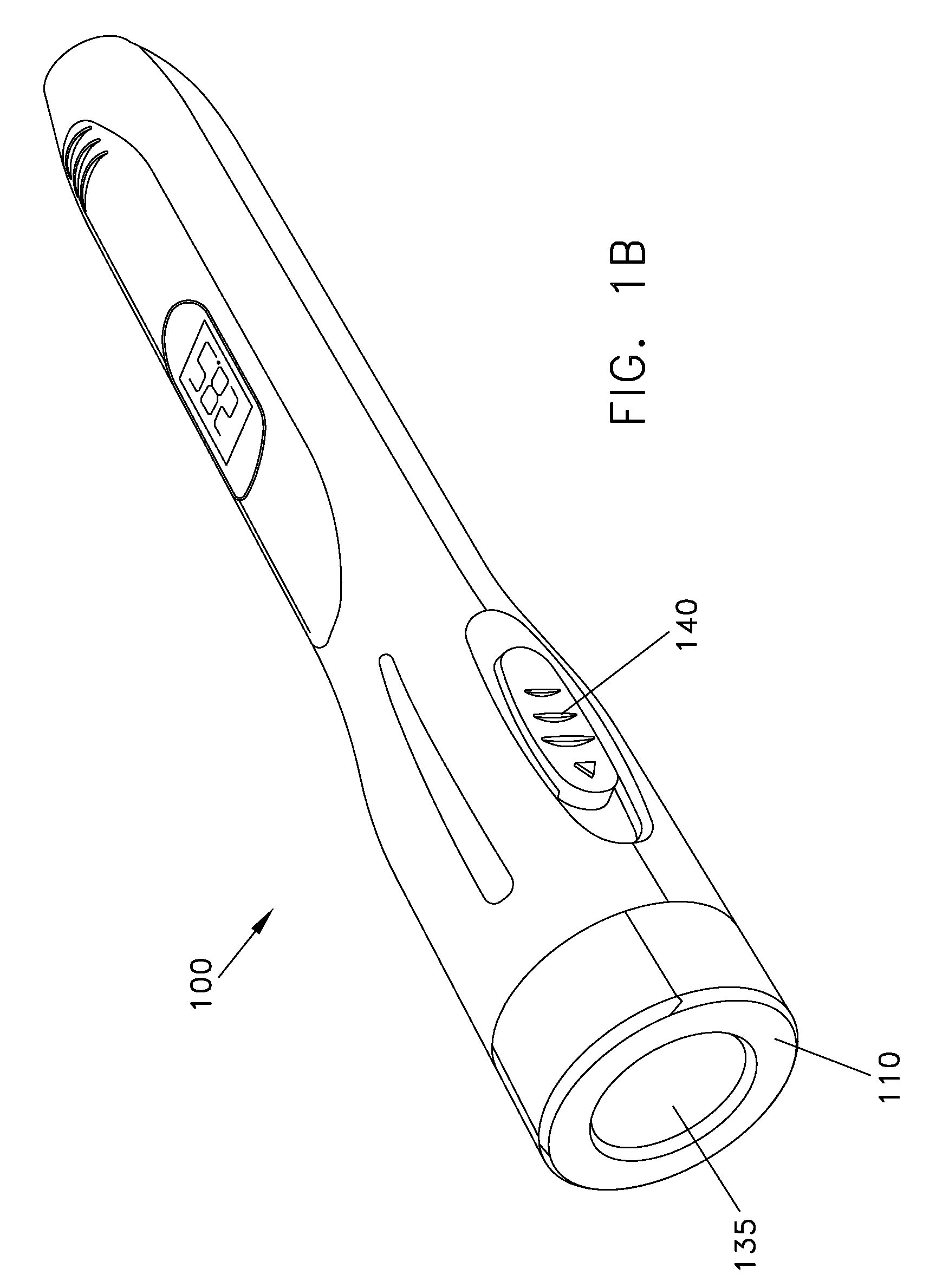
[0018]Now referring to FIG. 1A, a perspective view of an...


PUM


Abstract

A tire pressure gauge with a valve cap wrench is disclosed. A bore at one end of the tire pressure gauge may be used to grip and remove a valve cap mounted on a valve stem of a tire. A port at the other end of the tire pressure gauge may be used to measure air pressure in a tire. The measured air pressure may be displayed on a display on the pencil gauge. The cap wrench may have a collet to hold a valve cap and a switch to tighten and loosen grip on a valve cap. The cap wrench may also have a plunger to push a valve cap out of the pencil gauge.

Description

RELATED CASES[0001]This application claims benefit of and priority to U.S. Provisional Patent Application Ser. No. 61 / 000,702, filed Oct. 26, 2007, which application is hereby incorporated by reference herein in its entirety.FIELD OF THE INVENTION[0002]The present invention relates generally to a pressure gauge and more particularly to a tire pressure gauge with a cap removal wrench.BACKGROUND OF THE INVENTION[0003]Pressure gauges are conventionally used for measuring the pressure of a gas or a liquid, such as an air pressure. Tire pressure gauges, as an example, measure the inflation pressures of vehicle tires, such information being useful for maintaining optimal tire performance and avoiding unnecessary wear. Conventional tire pressure gauges are held in the hand, and require the user to locate a tire valve, unscrew a cap from the valve, and engage the tire pressure gauge with the valve. Tire valve caps are usually covered in a film of dirt, which comes off on the user's fingers ...

Claims


Application Information

Patent Timeline
Patent Type & Authority Patents(United States)
IPC IPC(8): B60C23/02
CPCG01L17/00B25B27/0057
Inventor BUCKNELL, CHRISTINE ANDERSON
Owner MEASUREMENT
Why Eureka
Try Eureka