Vibration damper having an amplitude-selective damping device

a damping device and vibration technology, applied in vibration dampers, springs, spring/dampers, etc., can solve the problem of structural complexity of amplitude-selective damping devices

Active Publication Date: 2010-05-25
THYSSENKRUPP BILSTEIN
View PDF14 Cites 7 Cited by
  • Summary
  • Abstract
  • Description
  • Claims
  • Application Information

AI Technical Summary

Benefits of technology

[0018]FIG. 5 shows a graph to explain the effect of the amplit

Problems solved by technology

A disadvantage of this known vibration damper is that the amplitude-selective damping device is structurally complex in design.
Therefore, in the event of low-amplitude vibration excitations, the pressure

Method used


Image

  • Vibration damper having an amplitude-selective damping device
  • Vibration damper having an amplitude-selective damping device
  • Vibration damper having an amplitude-selective damping device

Examples


first embodiment

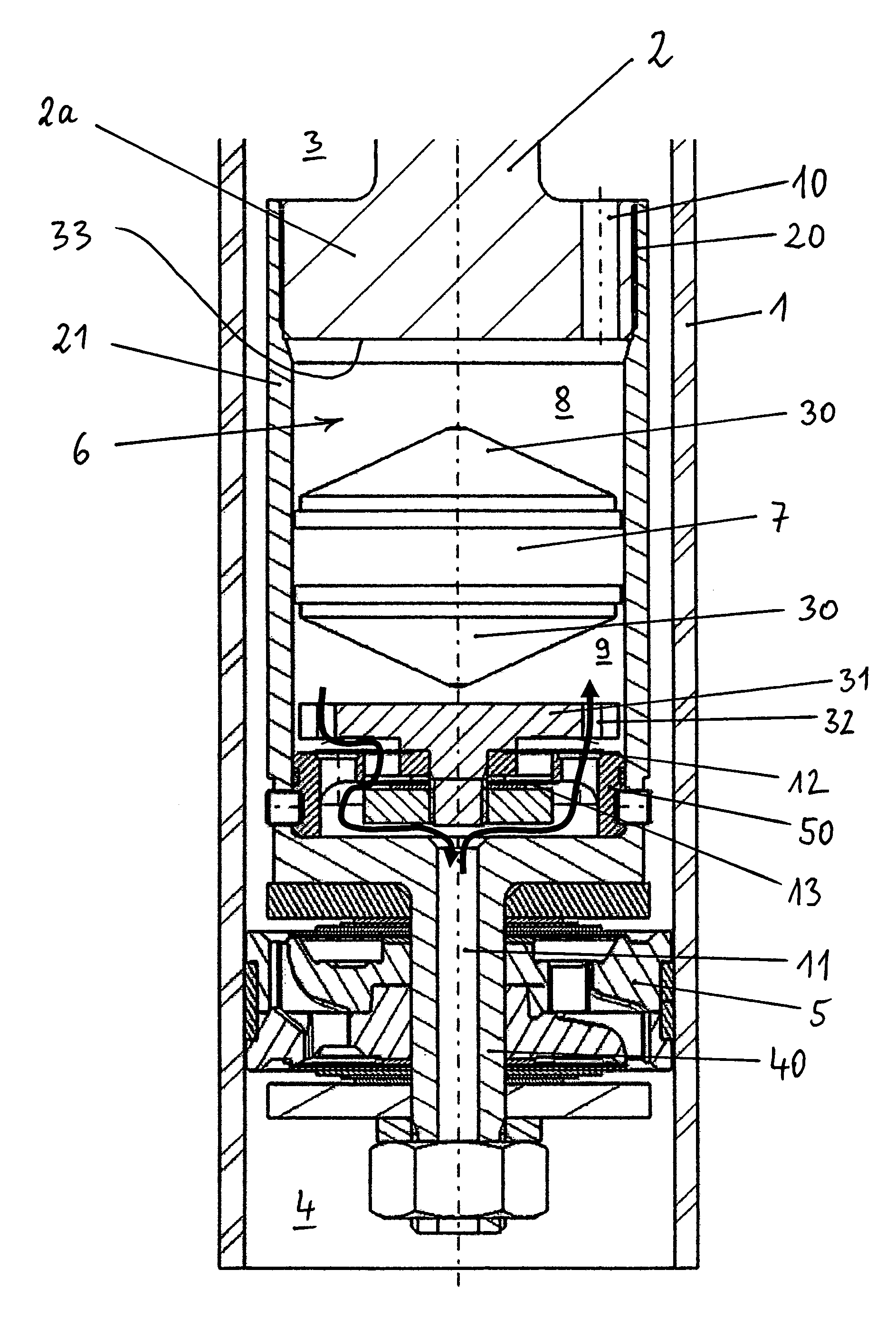
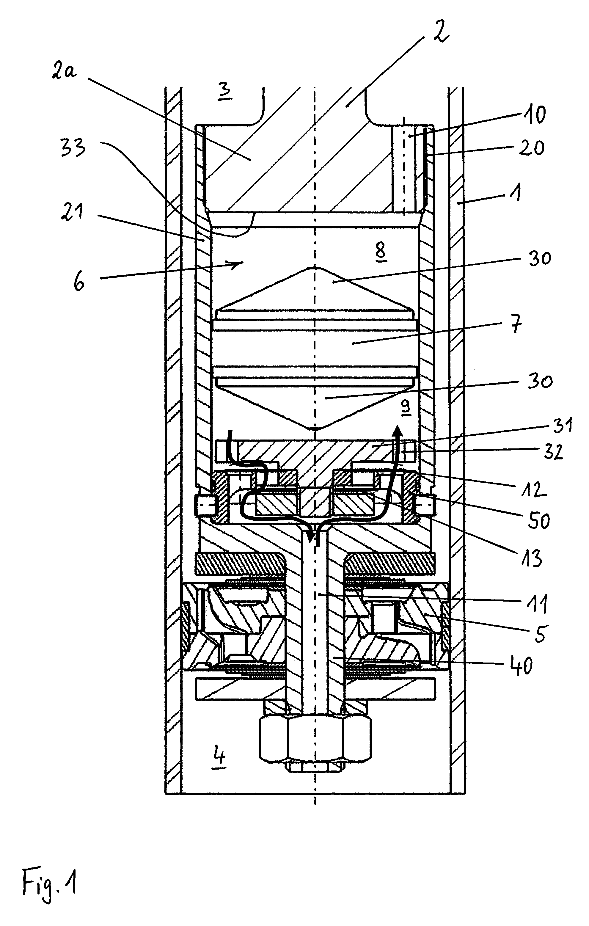
[0021]FIG. 1 schematically illustrates an axial half section of the vibration damper in accordance with the invention The arrows extending in different directions indicate different through-flow directions of the pressure limiting valves 12, 13 provided inside the bypass. The right-hand side of FIG. 1 illustrates the through-flow direction for the compression stage, whereas the left-hand side of FIG. 1 illustrates the through-flow direction for the extension stage.

[0022]A damping piston 5 is guided inside the damper tube 1 so as to be able to move in an oscillating manner. This damping piston 5 divides the inner space of the damper tube 1 into a piston rod-side working chamber 3 and a working chamber 4 remote from the piston rod. A housing which comprises a housing wall 21 is connected to the piston rod 2 via a thread 20. Disposed inside the housing is a separating piston 7 which divides the space 6, which is enclosed by the housing wall 21, into a piston rod-side chamber 8 and a ch...

second embodiment

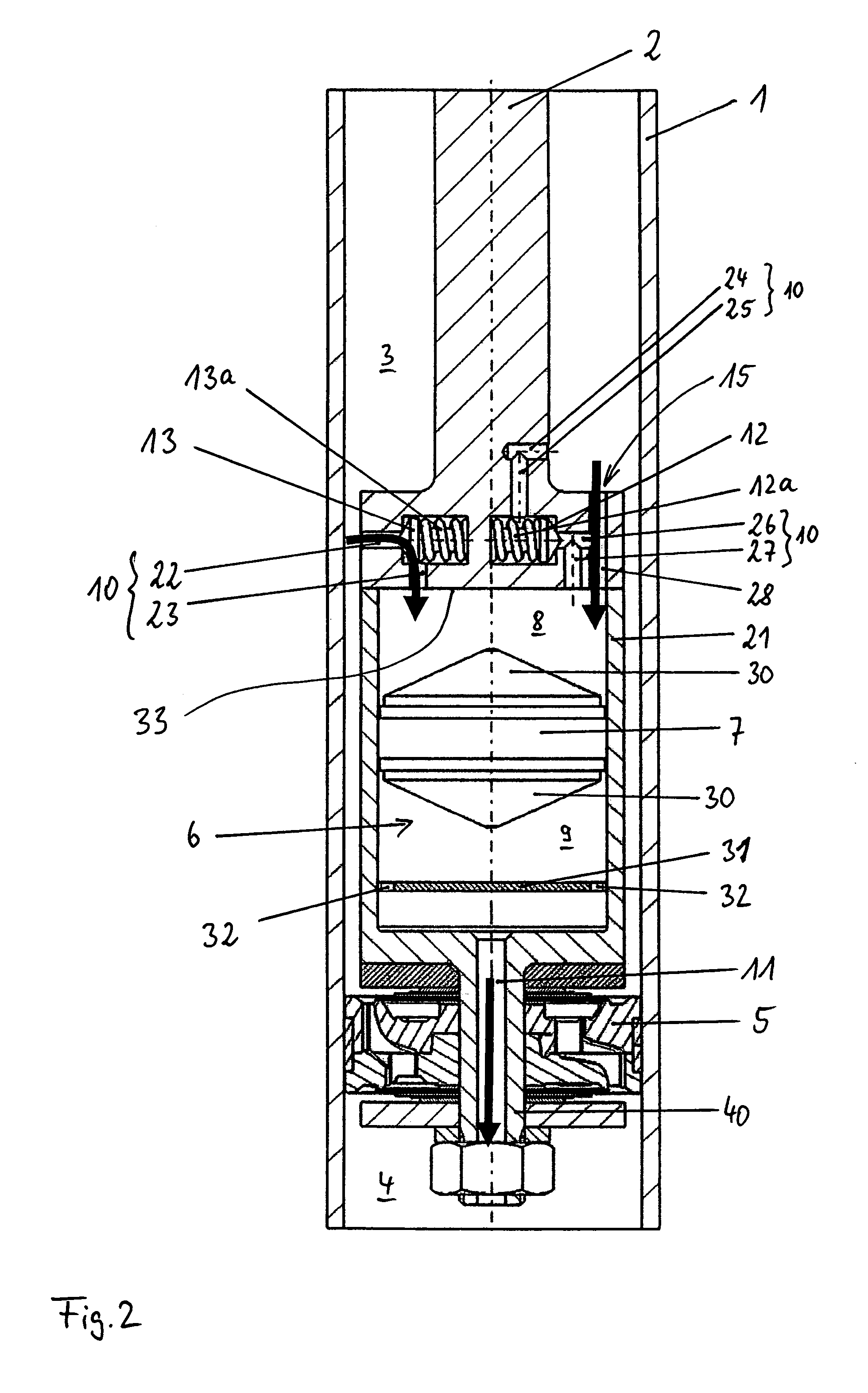
[0031]FIG. 2 illustrates the amplitude-selective damping device in accordance with the invention. Like components are designated by like reference numerals, as in FIG. 1. In comparison to the exemplified embodiment as shown in FIG. 1, the most important difference resides in the fact that the pressure limiting valves 12, 13 are not formed as disc valves but rather as spring-loaded seat valves.

[0032]The separating piston 7 is disposed inside the space 6 in such a manner as to be freely displaceable in the axial direction and divides the space 6 into the piston rod-side chamber 8 and the chamber 9 remote from the piston rod. On its periphery, the separating piston 7 lies in a sealing manner against the housing wall 21, so that the two chambers 8, 9 are sealed with respect to each other (similar to the embodiment as shown in FIG. 1).

[0033]In FIG. 2, the flow arrows shown illustrate how the damping fluid flows through the amplitude-selective damping device during extension stage damping...


PUM


Abstract

A vibration damper having a sensitive response behavior at very low amplitudes comprises a separating piston being disposed inside a bypass so as to move axially freely. The separating piston divides the bypass into two chambers mutually sealed from one another. Two valves are disposed in the bypass. The first valve acts in a compression stage as a pressure limiting valve and as a non return valve in an extension stage. The second valve acts as a pressure limiting valve in the extension stage and as a non return valve in the compression stage.

Description

BACKGROUND[0001]The invention relates to a vibration damper having an amplitude-selective damping device according to the preamble of claim 1.[0002]A vibration damper of this type is known from U.S. Pat. No. 5,248,014. A disadvantage of this known vibration damper is that the amplitude-selective damping device is structurally complex in design. Therefore, the separating piston comprises an annular circumferential groove and radially inwardly directed through-flow channels (shutter passages) which cooperate with through-flow bores (guide passages) in the housing wall defining the space which accommodates the separating piston. Furthermore, in the case of the known vibration damper, the separating piston is supported in both axial displacement directions via springs, so that it is disposed in such a manner as to be non-freely displaceable within the space accommodating it. Therefore, a minimum force which acts hydraulically upon the separating piston is required and this force must be...

Claims


Application Information

Patent Timeline
IPC IPC(8): F16F13/00
CPCF16F9/5126F16F9/3405
Inventor GOETZ, OLESAADEDDIN, KAISWEIMANN, CLAUSBRENDECKE, THOMAS
Owner THYSSENKRUPP BILSTEIN
Why Eureka
Try Eureka